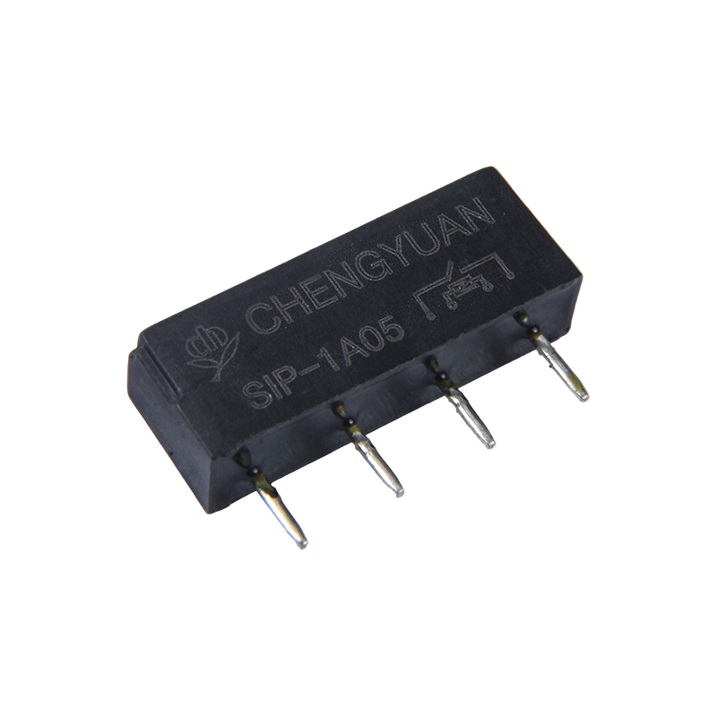
An engineer calls because a PLC output card has failed twice in the same week. The load is a 2.2 kW contactor whose coil pulls close to 3 A for a few milliseconds at every start, and the output is rated 0.5 A. A higher rated output module will not fix this. The correct answer is an interface relay between the controller and the coil, and the same answer applies to almost every inductive load in the panel.
Electrical PLC control is decided less by the program than by what happens at the output terminal. This article walks through the output stages of a controller, the relay or relay module that follows it, and the checks that keep a panel running well past its first year in service.
What a PLC Output Stage Can and Cannot Switch
A PLC output is not a power source. It is a switch that connects a field device to a supply you provide. The three common output stages behave very differently, and treating them as interchangeable is the fastest way to a burned board.
Direct switching capability of the three common PLC output stages and the loads each one suits.
| Output stage |
Switching element |
Loads it can drive directly |
Points to check |
| Relay contact output |
Sealed mechanical contact |
Indicator lamps, small contactors, solenoid valves, resistive loads up to about 2 A |
Contact life under inductive loads, inrush current, minimum load needed for reliable contact wetting |
| Transistor output |
NPN or PNP semiconductor |
DC solenoids, LED indicators, solid state input modules |
Polarity, common anode or common cathode wiring, no galvanic isolation, leakage current |
| Triac output |
AC semiconductor switch |
AC solenoid valves, small AC heaters |
Residual leakage that can keep a load partly energised, minimum load current, heat at the module |
The pattern is simple. Resistive and low current loads can sit directly on an output. Anything with a coil, a capacitor input, or a filament that draws several times its steady state current at switch on belongs behind an interface relay.
Why an Interface Relay Still Earns Its Place
Removing the interposing relay saves a few centimetres of rail and a few dollars per point. In most industrial cabinets it comes back after the first service call, for three reasons.
Galvanic separation between logic and field
The relay coil is driven by the PLC output, and the contact carries the field current. A short circuit in a valve cable therefore stops at the relay instead of reaching the output board. On a machine with forty outputs, that difference is one relay versus one controller.
Inrush, kickback, and contact material
A contactor coil can draw five to ten times its holding current for the first milliseconds and then throw a reverse voltage spike when it opens. A relay rated 16 A at 250 V AC with silver tin oxide contacts absorbs that duty, and a replacement costs a fraction of an output card. For dry circuits that carry almost no current, gold plated contacts are the better choice, because plain silver contacts can develop an oxide film that stops low level signals from passing.
Serviceability and spare parts
A rail mounted or socket mounted relay is replaced in two minutes during a weekend shutdown. A failed output module usually means a stopped line, a delivery delay, and a program download that nobody wants to perform at two in the morning.
Choosing an Interface Relay for a PLC Output
Selection comes down to a handful of numbers. Work through them in this order and the specification usually writes itself.
- Coil voltage and must-operate voltage. A 24 V DC coil is the standard in machine control panels. Confirm that the must-operate voltage is below the minimum output voltage of the PLC supply, and that the must-release voltage is above any residual leakage from a triac or transistor output.
- Coil current against the output rating. A 24 V DC coil rated 0.4 W draws roughly 17 mA. Derate the PLC output to about 60 percent of its stated rating when the load is inductive, and add up the total current of all outputs sharing one common terminal.
- Contact rating and load type. Match the rating to the actual load, not to the label on the panel. A 16 A contact driving a 1 A solenoid is fine, while a 2 A contact driving a 3 A coil is not.
- Inrush current. Look for a contact rating that states the short duration value, or add a series resistor or a thermistor for high inrush loads such as large contactors and capacitor banks.
- Duty cycle and life. Mechanical life of several million operations is normal. Electrical life under a contactor coil load is much shorter and should be compared with the number of starts the machine performs per day.
If you want a refresher on the mechanics behind the coil and the armature, this explainer covers what a general purpose electromagnetic relay does in plain terms.
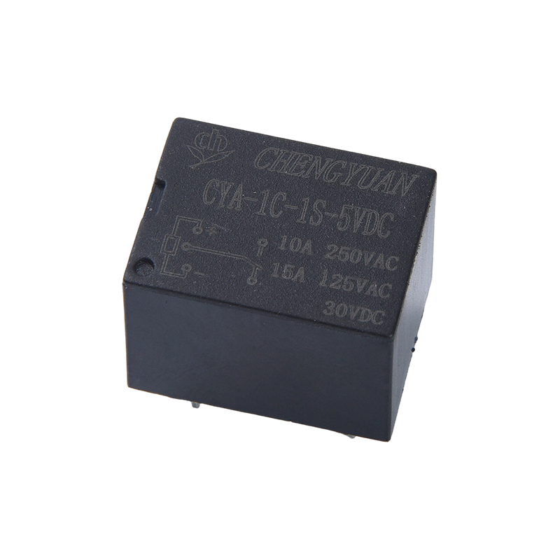
 CYF1 PCB Mounted Electromagnetic Relay for General Purpose SwitchingPCB-mounted single-pole relay with 10 A or 16 A contact options, 3-48 VDC coils and a compact 5-pin footprint for high-density switching.View Product →
Relay Modules and DIN Rail Wiring Practice
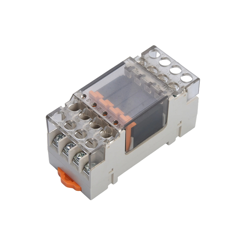
A relay module packages the relay, the coil terminals, and the screw connections into a single rail mounted unit. Modules built around the same relay family in 10 A and 16 A contact versions share a footprint, so a panel can be uprated later without redrilling the rail or redrawing the layout.
Wiring practice matters as much as the module itself. Use ferrules on stranded wire, keep coil wiring in a separate duct from contact wiring wherever the panel layout allows, group commons by output card rather than by terminal position, and label every output with its program address. A clear drawing and one spare relay of each type will prevent more downtime than any diagnostic function inside the controller.
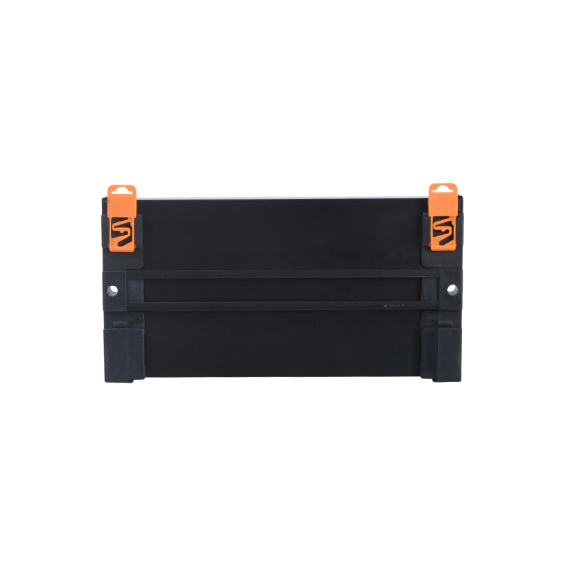 MCYF1 DIN Rail Magnetic Latching Relay ModuleDIN rail module using latching relays for zero static power and power-off state memory, with up to 16 channels and 16 A per channel.View Product →
Magnetic Latching Relays in PLC Control
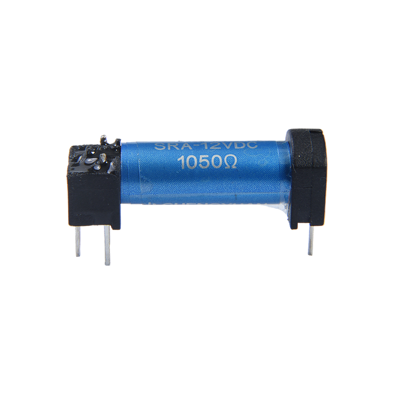
A magnetic latching relay holds its last position with no coil current. That property is useful in two situations: when a machine must keep the state of a valve or an indication through a power failure, and when dozens of coils left energised all day are adding heat and load to the supply.
Latching relays need short pulses rather than continuous signals, so the program must set and reset them deliberately, and commissioning has to include an explicit reset step because the contacts can arrive in either position. Panels that use them usually keep a standard interposing relay in series so that the PLC can also force a load off when the sequence requires it.
 CYF1-S Magnetic Latching Relay for Low-Power State MemoryBistable PCB relay that holds contact state without coil power, suited to energy-saving, backup and power-outage retention designs with up to 16 A switching.View Product →
Where PLC Control Interfaces Fail in the Field
- Welded contacts after months of repeated inrush from a contactor coil.
- A load that never fully switches off because a triac or transistor output leaks a few volts.
- Coils wired to the wrong common terminal, so two outputs fight each other.
- No flyback diode on a DC coil, which shortens both contact life and output stage life.
- Loose ferrules and machine vibration, producing intermittent contacts that are blamed on the program.
- Relays pushed into a socket by one pin only, working on the bench and failing on the machine.
Commissioning Checks Before Handover
- Measure the coil voltage at each relay with the field supply set to its lowest expected value.
- Force outputs one at a time from the programming software and confirm that only the intended relay operates.
- Verify continuity at the load terminals with each relay energised, and confirm that the contact opens when the output is released.
- Check for leakage voltage with all outputs off, especially on triac and transistor outputs.
- Run the panel for 30 minutes and check coil and contact temperatures. A warm coil is normal, a hot contact is not.
- Record the relay model, contact configuration and program address on the panel drawing, and keep one spare of each type in the cabinet.
Ningbo Chengyuan Chuangke Electronics has been manufacturing relays in Yinzhou, Ningbo since 1996, and today supplies general purpose electromagnetic relays, reed relays, magnetic latching relays and rail mounted industrial control modules. You can read more about the company and its manufacturing background on the site.
Send a coil voltage, a load type and a switching current, and the interface can be matched to a relay or module that fits the panel instead of the catalogue page.

 English
 中文简体
 Español