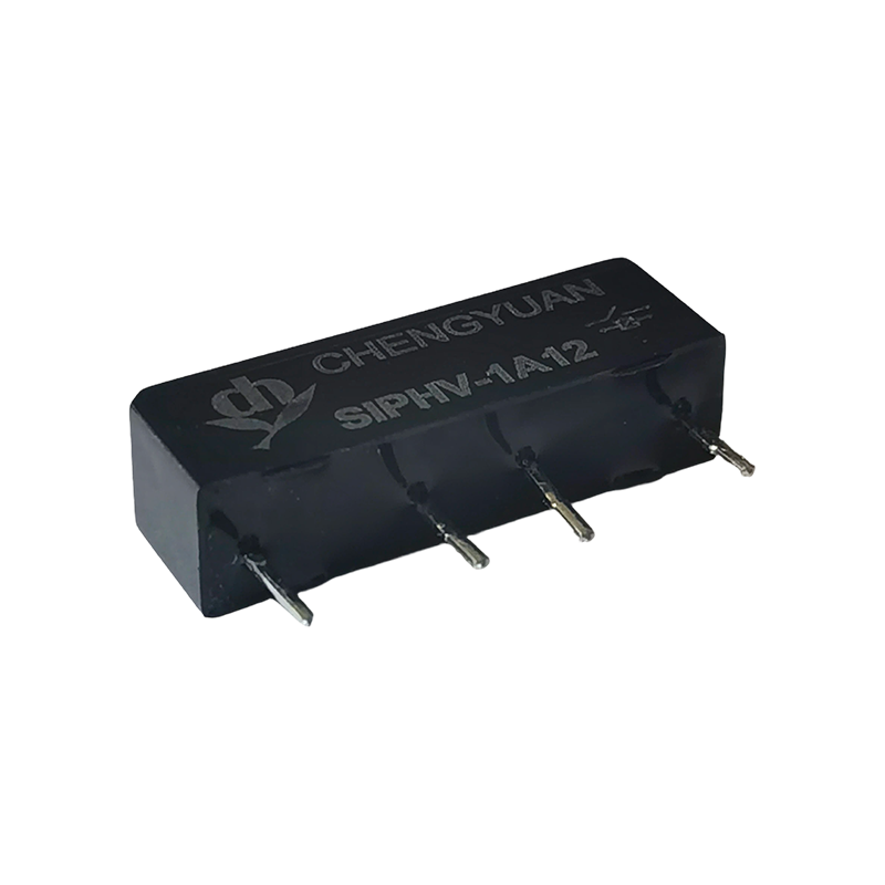
A 15 kW three phase motor on a 400 V supply draws roughly 30 A. Inside its starter there are two devices with two separate jobs. The contactor makes and breaks the motor current. The overload relay protects the motor. Keeping that division clear settles most of the confusion around electrical contactors. A contactor is a load switching device, not a protective device, and it is built to be inspected and replaced when its contacts wear. Coil voltage, utilisation category, auxiliary contacts and mounting all follow from that one idea.
What an Electrical Contactor Actually Does
An electrical contactor is an electromagnetically operated switch built for repeatedly making and breaking a power circuit under load. Current through the coil pulls in an armature, the main contacts close, and one or more auxiliary contacts change state at the same time. Removing the coil current lets a spring return the armature and open the main contacts.
The arc that forms when a loaded circuit opens would destroy a plain contact pair within a few thousand operations, so full size contactors carry arc chutes or splitter plates. These stretch, cool and divide the arc until it cannot restrike.
Three limits matter in practice. A contactor provides no overload protection, so it is always paired with a thermal or electronic overload relay. It is not a disconnector, so it cannot serve as the isolation point for maintenance work. And its rating is not a single number: the same frame carries different currents for resistive loads, for motors switched while running, and for motors switched during inching or reversing.
Contactor or Relay: Where the Line Actually Sits
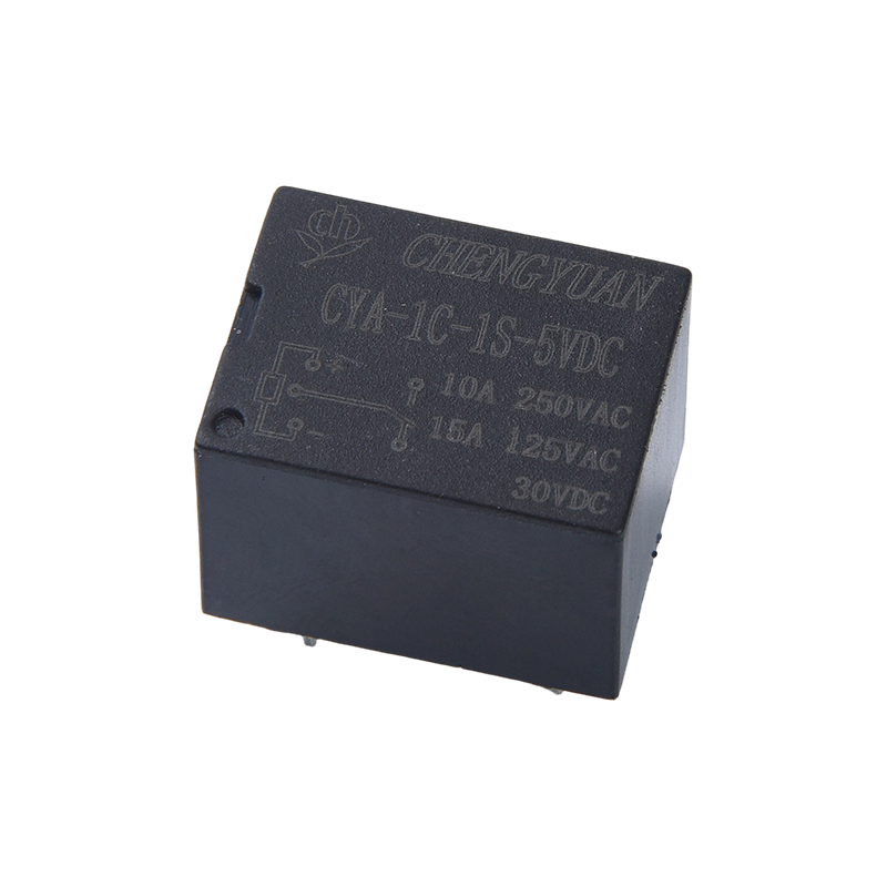
Both devices are electromagnetically operated switches, and both appear in the same cabinets, which is why the terms get mixed up. The differences that matter are current level, arc control and duty.
Table 1: How a contactor and a control relay divide the work in a low voltage panel.
| Property |
Contactor |
Control relay |
| Typical main contact rating |
9 A up to several hundred A |
1 A to 16 A |
| Product standard |
IEC 60947-4-1 |
IEC 60947-5-1 or IEC 61810 |
| Arc control |
Arc chutes and splitter plates |
Small contact gap, no arc chute |
| Mounting |
DIN rail or panel with dedicated base |
PCB, socket or DIN rail |
| Coil burden |
High inrush, several VA to tens of VA |
Low, often under 1.5 VA |
| Typical duty |
Motor starting, resistive heating loads |
Logic, signalling and pilot duty |
| Expected life |
Depends heavily on utilisation category |
Millions of operations at low load |
Below roughly 20 A the decision is usually about duty cycle and load type rather than size. A high current relay such as the CY T90 series, rated 30 A or 40 A in an SPDT arrangement, can replace a small contactor on resistive or lightly inductive loads and keep the panel footprint small. Where the load is a motor, the arc chute in a contactor still earns its space.
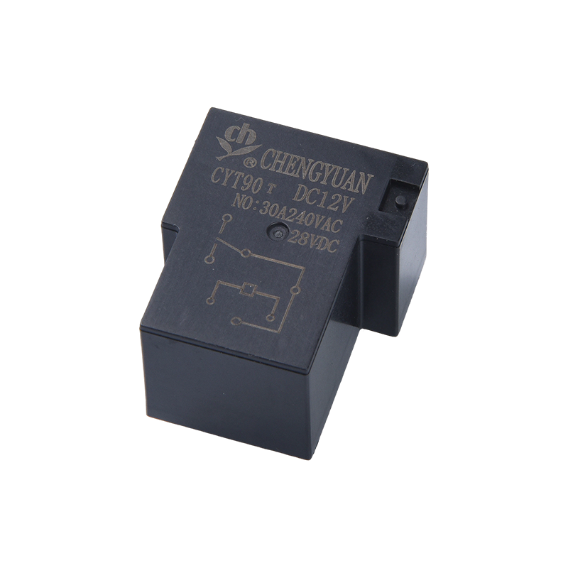 CYT90 T90 High-Power SPDT Relay for Compact Load SwitchingCompact high-power SPDT relay for 20A/30A switching, useful where resistive or lightly inductive loads need a small panel footprint.View Product →
Utilisation Categories Decide Service Life
The large current printed on a contactor nameplate is usually the thermal current, the value the device can carry without overheating. It is not the current the contacts can switch repeatedly for years. That number comes from the utilisation category.
Table 2: IEC utilisation categories and what they mean for contact life.
| Category |
Typical load |
Switching severity |
| AC-1 |
Non inductive or slightly inductive loads, resistive heating |
Light |
| AC-3 |
Squirrel cage motors, switching while running |
Moderate, most common |
| AC-4 |
Squirrel cage motors, inching, plugging and reversing |
Severe |
| DC-1 |
Non inductive DC loads |
Light |
| DC-3 |
Shunt wound DC motors, starting, plugging, inching |
Severe |
| DC-13 |
DC electromagnets and coils |
Moderate, with high inductance |
Two consequences follow. First, always compare like with like: an 18 A AC-3 device is not an 18 A AC-4 device, and datasheets show that reduction directly. Second, ambient temperature and enclosure size shift the usable current. A contactor rated for 60 degrees Celsius in free air loses capacity inside a sealed cabinet, so the derating curves should be read before the order is placed.
Coil Circuits: Interface Relays and Modules Do the Switching
Contactors are normally driven by a PLC, and that is where the coil circuit runs into trouble. A transistor output rated 0.5 A at 24 VDC cannot drive a 230 V coil that draws several VA when sealed and far more at the instant of pull in. The usual answer is an interface layer: the PLC output drives a small relay, and that relay contact switches the contactor coil.
A rail mounted module with a 24 VDC coil and changeover contacts, such as the MCYF1 series, performs that conversion in a single DIN rail slot and keeps the wiring tidy when a panel holds twenty or thirty starters.
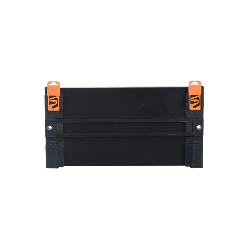 MCYF1 DIN Rail Relay Module with Magnetic Latching RelaysDIN rail-mounted module using magnetic latching relays, offering multichannel 10A–16A switching for tidy industrial control panels with low static power.View Product →
Protection on the coil side is just as important. DC coils need a freewheeling diode or an RC network, and AC coils need a varistor or an RC snubber. Without them, the collapsing field at switch off produces a transient that eventually takes out the PLC output rather than the contactor.
Matching the Control Side to the Switching Side
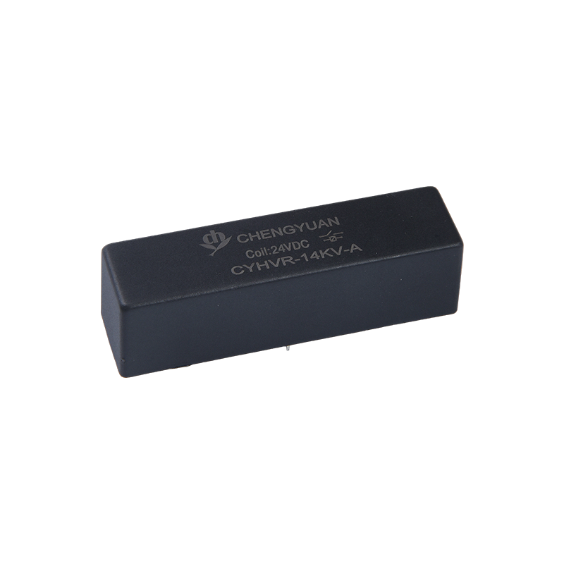
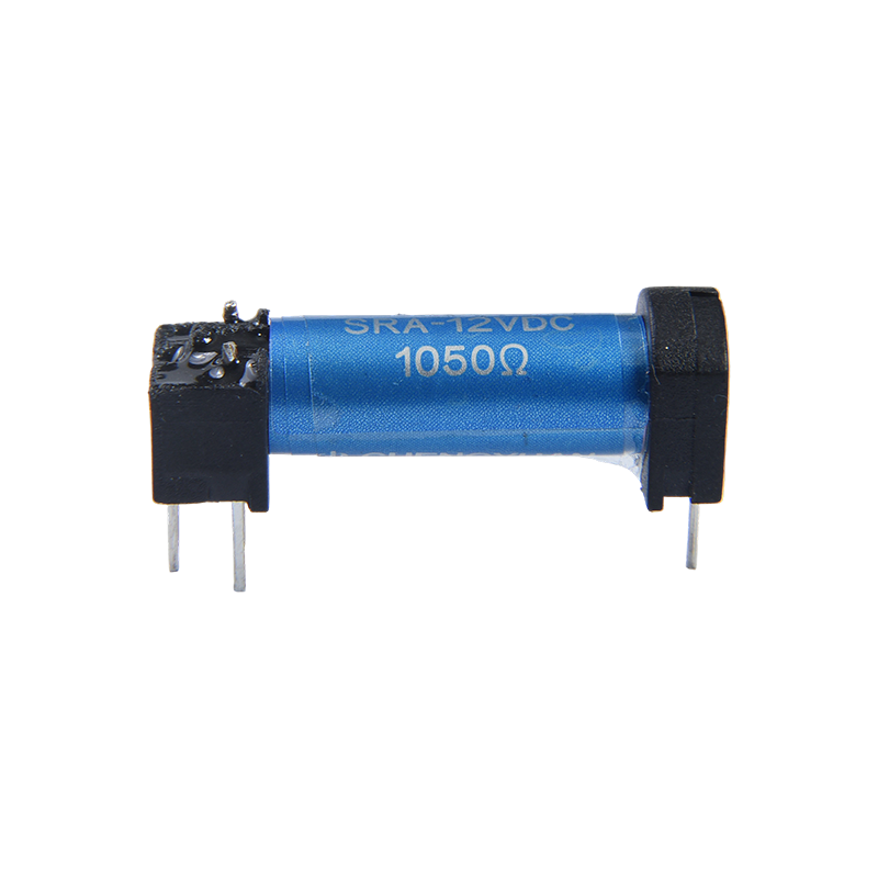
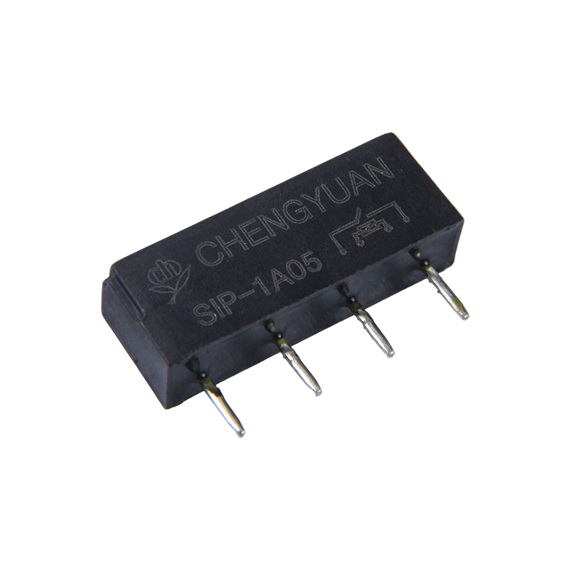
Not every control function needs an ordinary relay. Three families cover most practical cases. General purpose electromagnetic relays handle standard pilot duty. Magnetic latching relays hold their last state without continuous coil power, which suits step sequences, memory functions and panels where coil consumption adds up. Reed relays switch high voltage or high frequency signals at low current and offer very long mechanical life.
Mixing them carelessly causes trouble, because a latching relay that keeps state after a power failure is helpful in a sequence and dangerous in an emergency stop path where the circuit must drop out. Types such as the CYF3S series, a 14F latching relay rated 16 A, show the trade off clearly: two stable states, no holding current, and the need to design the reset logic deliberately.
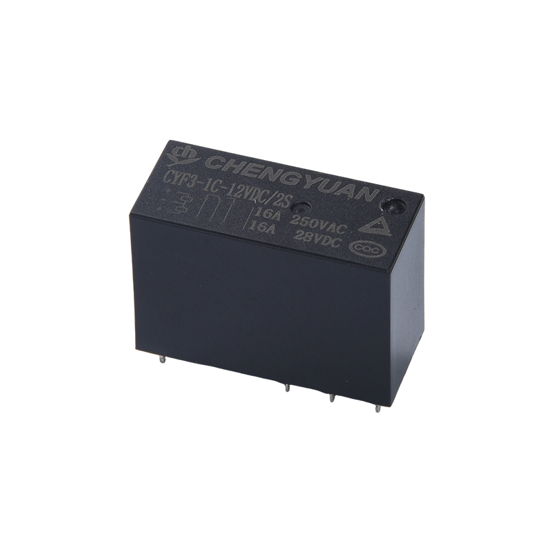 CYF3-S 14F Magnetic Latching Relay for Zero-Power SwitchingCompact latching relay that maintains contact state after control power is removed, useful for PCB assembly where power-off memory is required.View Product →
A Short Specification Checklist
- Identify the load and the utilisation category, not only the thermal current.
- Confirm the main contact current at that category, then apply derating for ambient temperature and enclosure.
- Fix the coil voltage and supply type, AC or DC, and check the inrush burden on the driving output.
- Count the auxiliary contacts needed for sealing, interlocking and status feedback.
- Check terminal size, cable cross section, mounting and the space left for arc chutes.
- Verify short circuit coordination with the upstream protective device.
- Estimate operations per hour and set a contact inspection or replacement interval.
Failure Modes You Can Read From the Panel
- Coil burnout usually points to sustained undervoltage, an overvoltage transient or the wrong coil voltage.
- Welded main contacts follow closing on a short circuit or a very high inrush load.
- Chatter comes from a sagging control supply, a loose terminal or an output that was never rated for the coil.
- Fast contact wear on motors is nearly always the wrong utilisation category, such as reversing duty on an AC-3 rated device.
- Uneven wear across the three poles suggests phase imbalance or a loose connection on one leg.
Sourcing Contactors and Control Relays
Ask for more than a current rating. Useful datasheets include coil data for AC and DC, mechanical and electrical life curves, derating information and the terminal arrangement. It is also worth asking what changes between a sample and a production run, because contact material, plating thickness and spring force move the life figures more than the headline rating does.
The company behind this site, Ningbo Chengyuan Chuangke Electronics, has manufactured relays in Yinzhou, Ningbo since 1996, and its company profile describes a range covering general purpose electromagnetic relays, reed relays, magnetic latching relays and rail mounted industrial control modules. Its patents from 2012 to 2014 include a snap fit magnetic latching bistable mechanism, a push pull magnetic latching relay and a frame type thermocouple relay. If you need coil data for a 24 VDC interface circuit or a 16 A contact for a small starter, you can request a quote and match the parts to your panel.
Contactors and relays are not competing answers to the same question. The contactor handles the load, the relay handles the logic, and a panel runs reliably when each device is chosen for the duty it will actually see.

 English
 中文简体
 Español