1. Advantages
Fully Sealed Contacts: The reed switch is sealed in an inert gas, protecting the contacts from dust and oxidation, providing long-term stable contact resistance and extremely high reliability.
High-Speed Switching Performance: The small mass of the reed switch allows for fast operation (switching time is typically in milliseconds), suitable for applications requiring rapid signal sampling or switching.
Low Power Consumption and High Isolation: Low coil drive power consumption, high insulation resistance and voltage withstand between contacts and coil, achieving excellent signal isolation and anti-interference capabilities.
2. Key Features
Contact Capacity: 0.5A @ 125VAC / 24VDC, designed specifically for switching low-level signals, sensor signals, or small current loads.
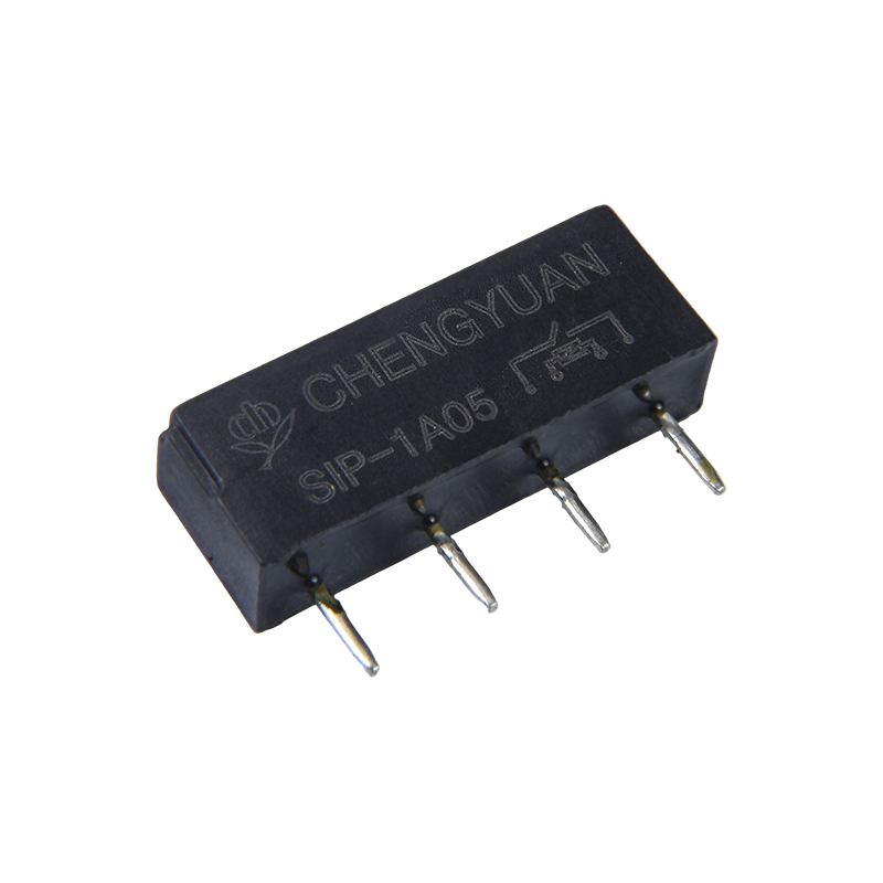
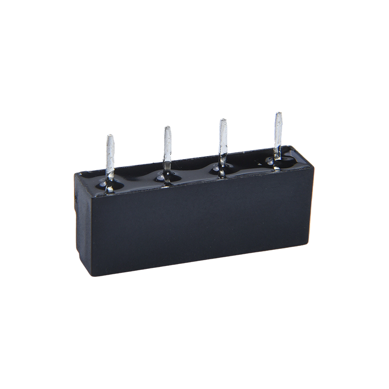
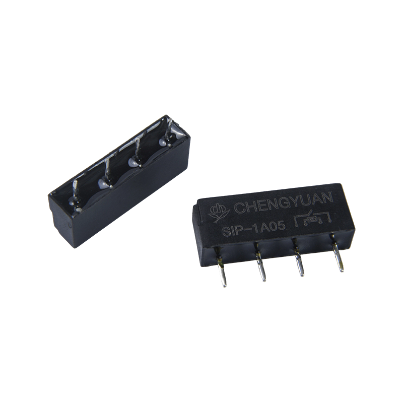
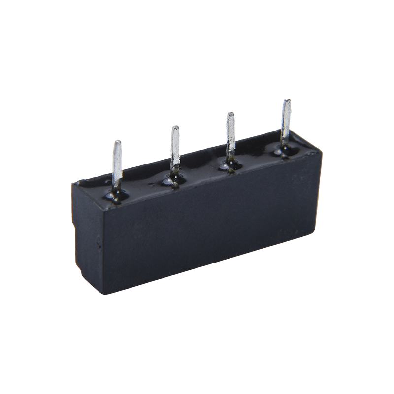
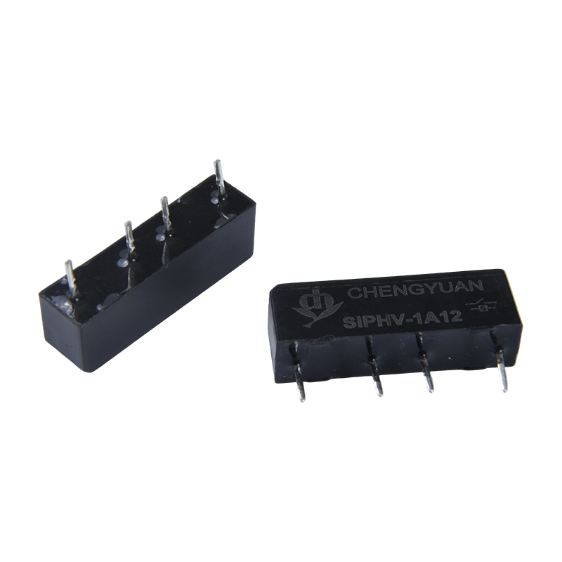
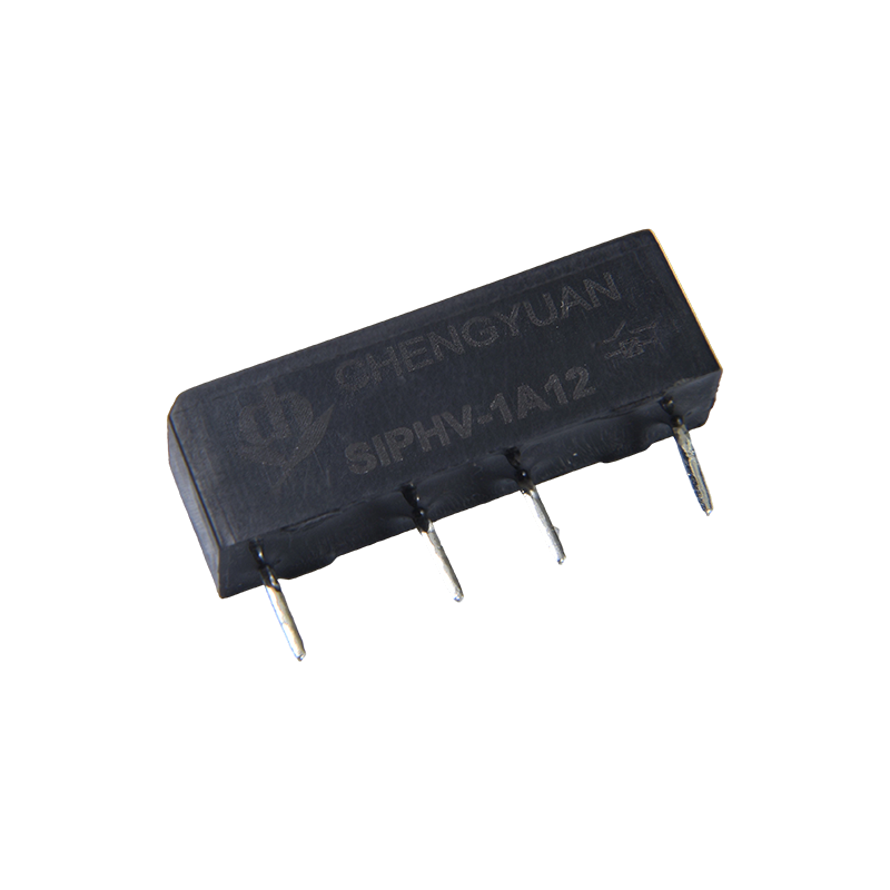
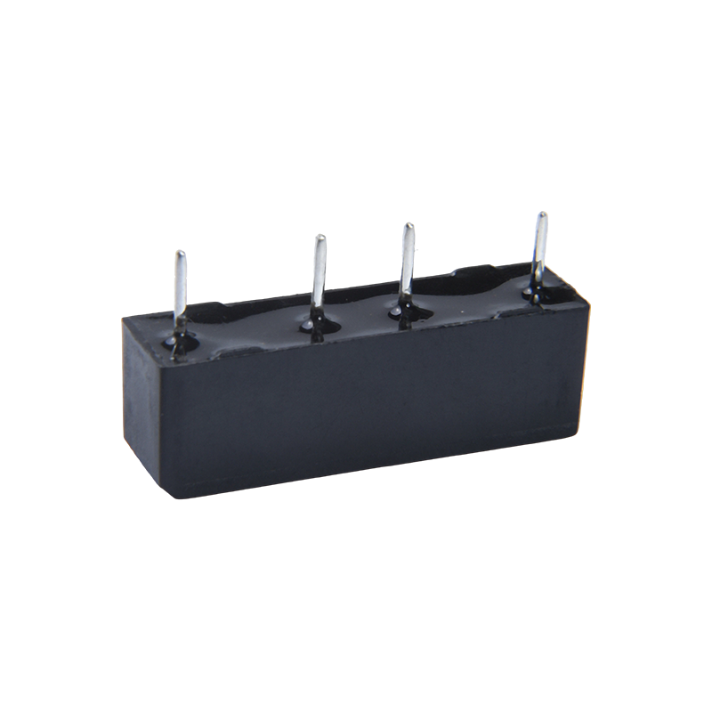
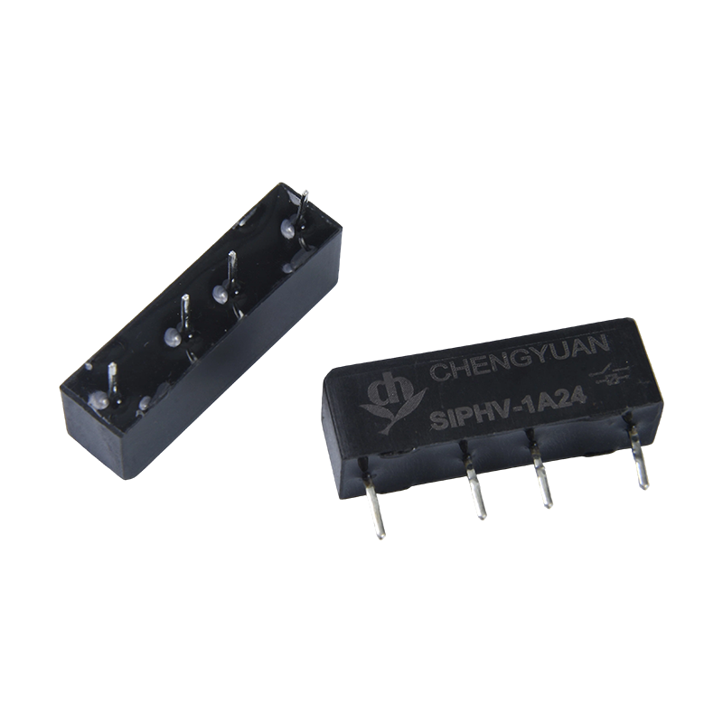
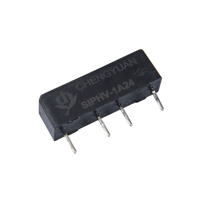
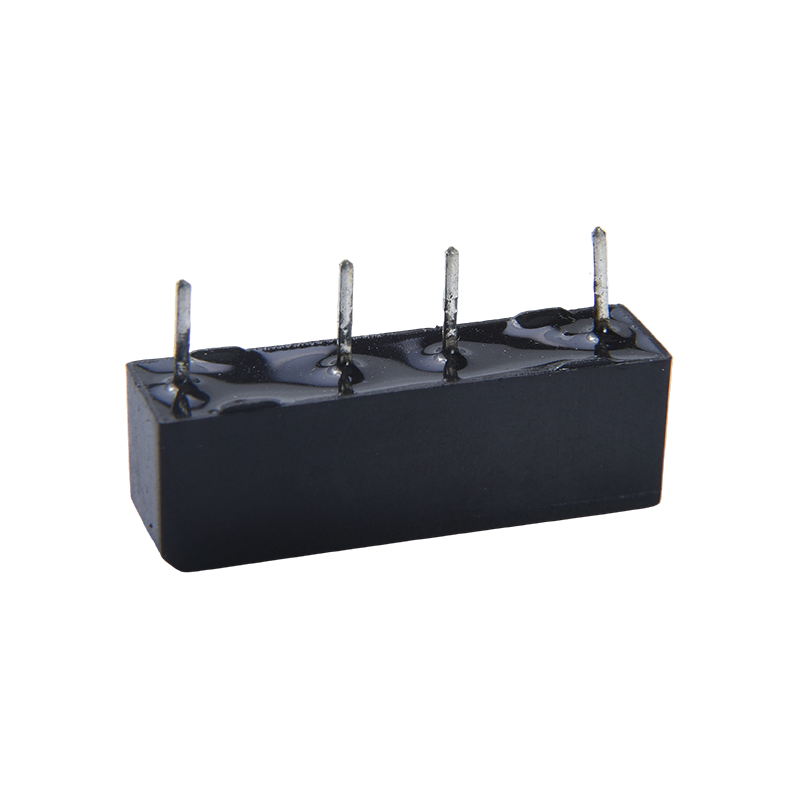
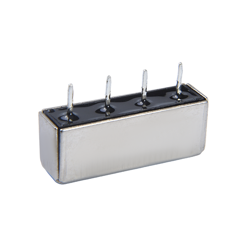
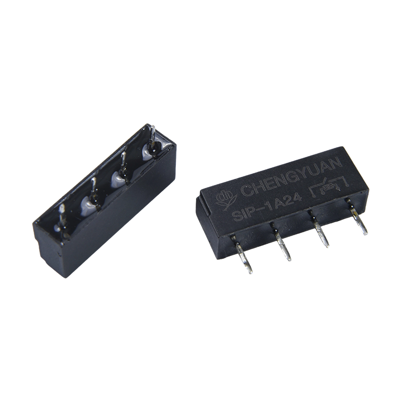
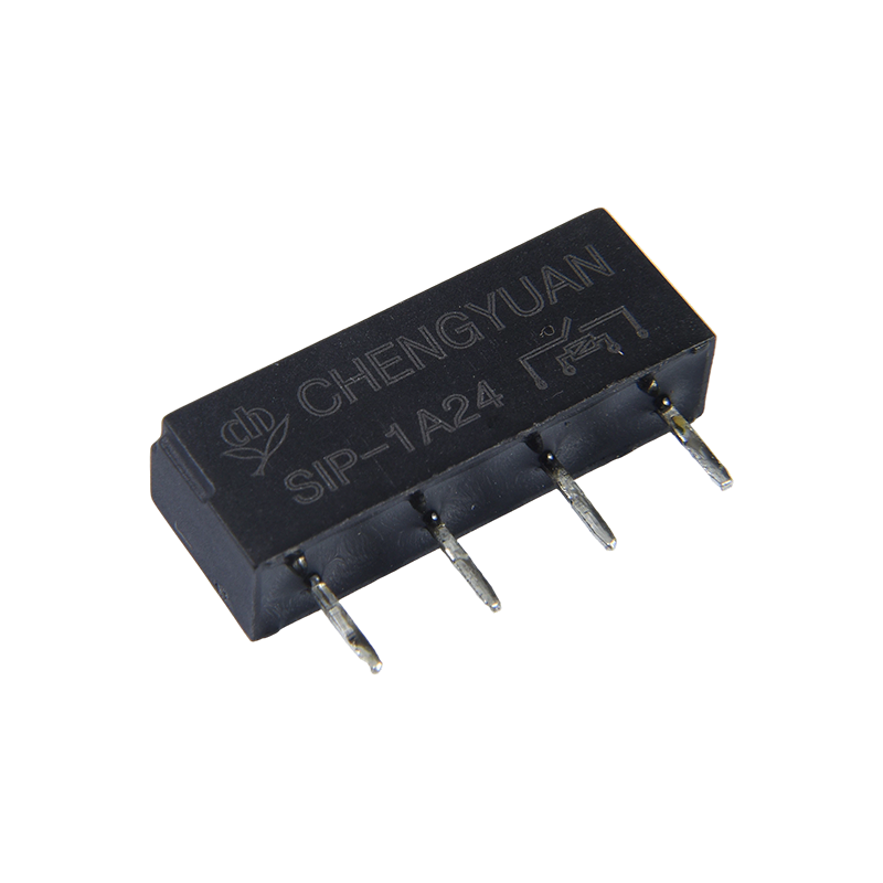
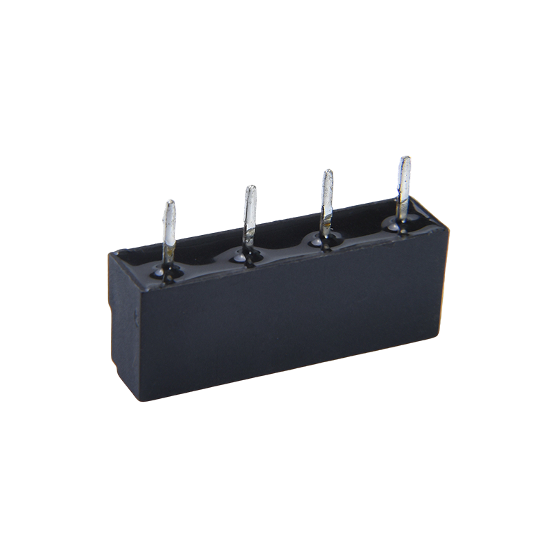
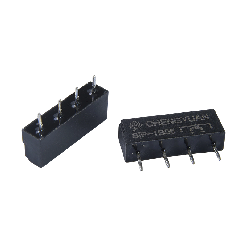
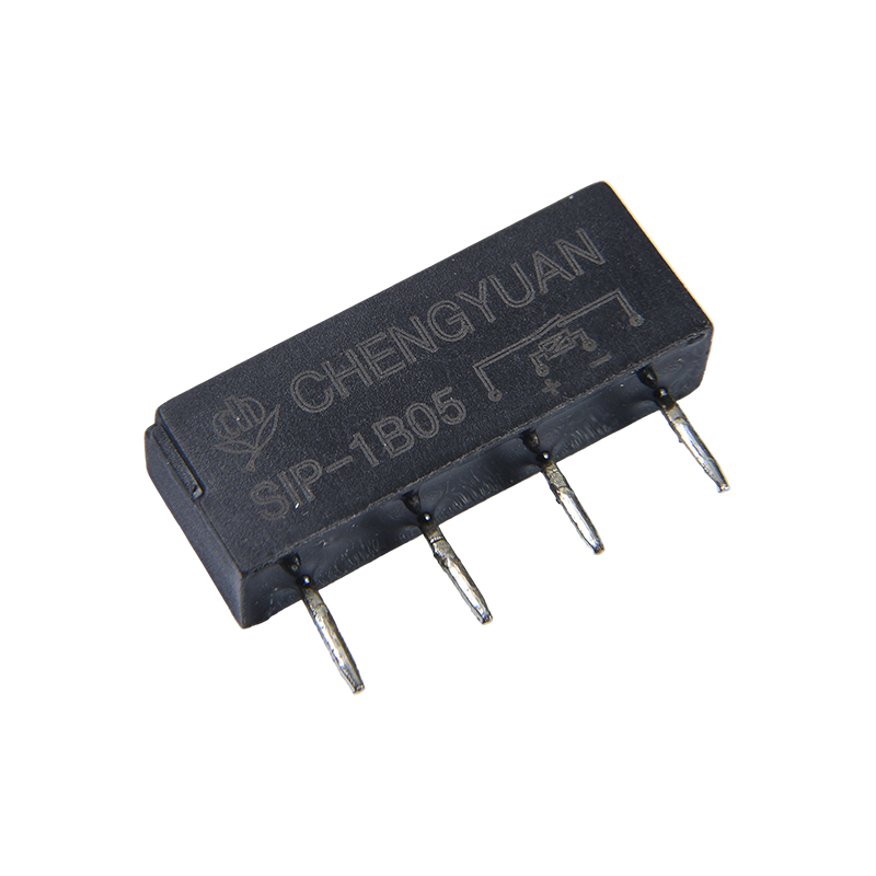
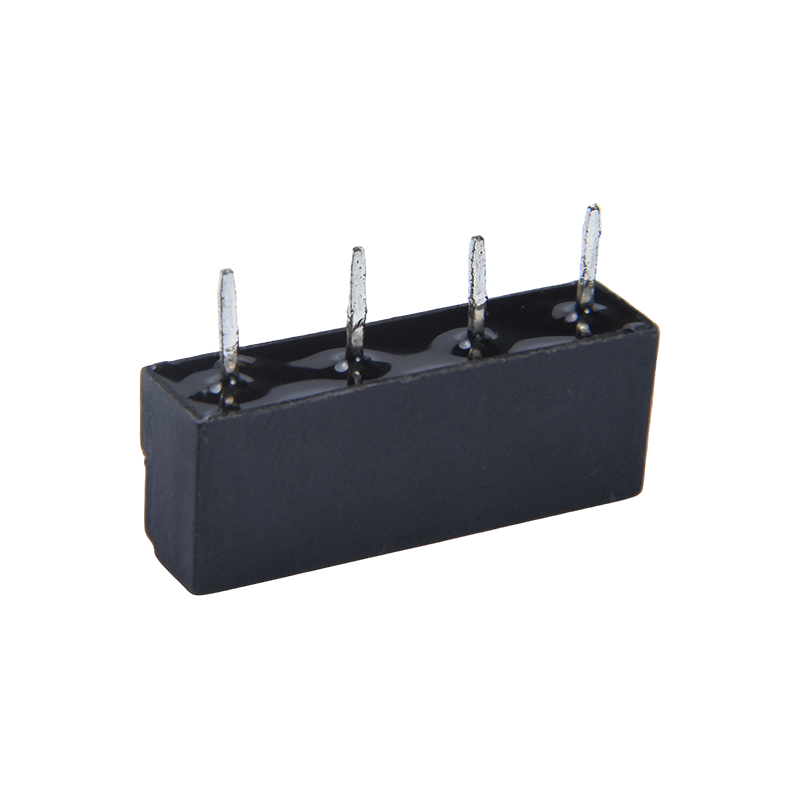
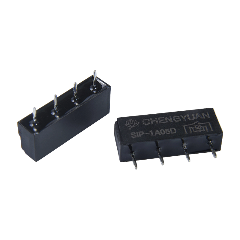
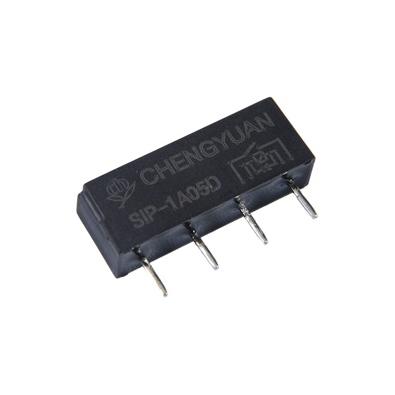
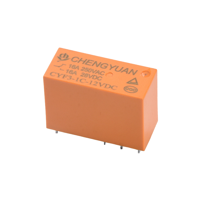
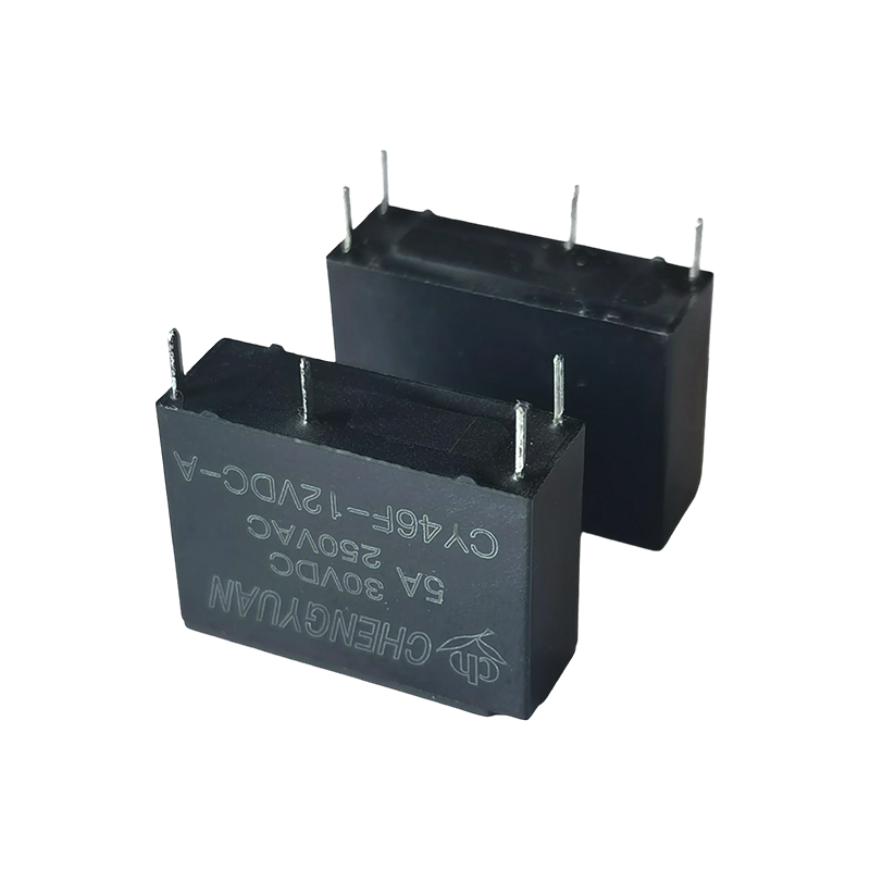
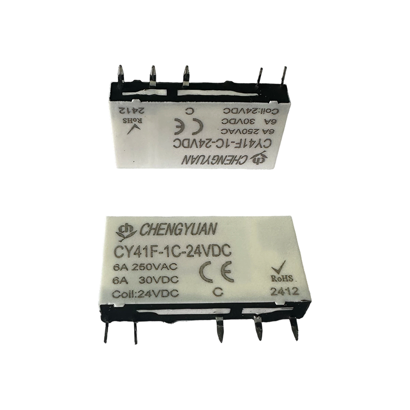
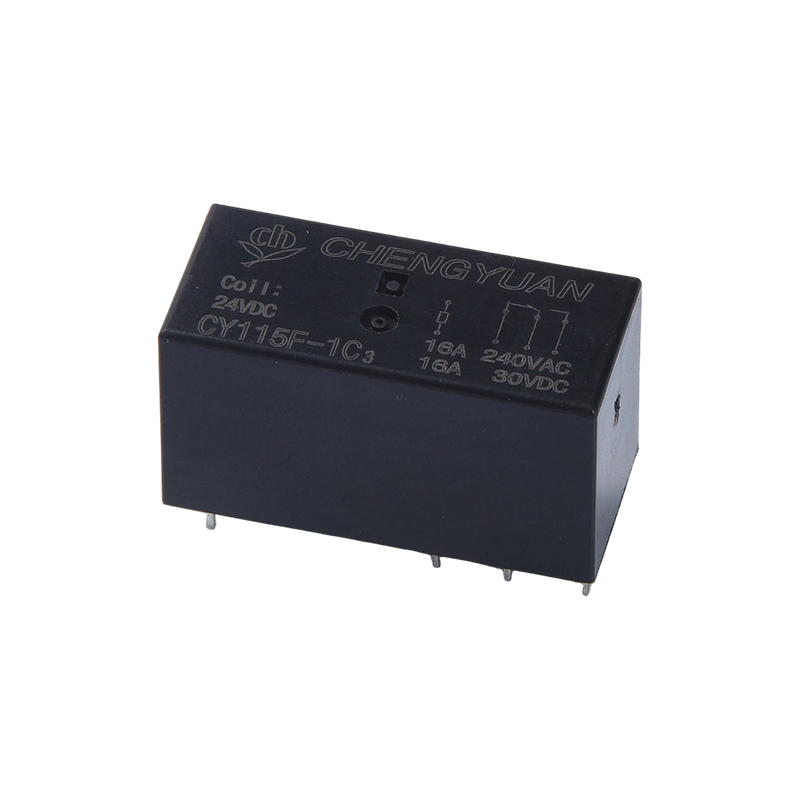
Compact Package: SIP (Single In-line Package) pin design with standard pin spacing, saving PCB space and facilitating automated assembly or insertion.
Wide Driving Voltage: The coil supports 3 to 24VDC voltage, compatible with common logic levels and control voltages.
Long Service Life: Due to sealed protection, the mechanical and electrical life under rated load is significantly higher than open-type electromagnetic relays of the same size.
3. Main Applications
Test and Measurement Equipment: Used in high-precision multimeters, data acquisition cards, and automatic test equipment (ATE) for signal path switching and multiplexing.
Communication and Security: Integrated into programmable switches, security alarm systems, and access control systems for signal isolation and interface switching circuits.
Medical Electronics: Used in medical monitoring equipment to switch low-level analog signals such as bioelectrical signals, requiring high isolation and low noise.
Industrial Control Signal Isolation: In PLC analog input modules and sensor interfaces, it provides electrical isolation and protection between field signals and control systems.
Contact Data
|
Type
|
SIP
|
|
Contact material
|
Ru/Rh
|
|
Contact resistance
|
≤ 100mΩ Max.(at 1A 16VDC)
|
|
Rated load (Resistive load)
|
0.1A125VAC /0.5A 24VDC
|
|
Max. switching current
|
0.5A
|
|
Max. switching voltage
|
200VAC
|
|
Max. switching power
|
10VA(AC)/10W(DC)
|
|
Characteristics
|
|
Operate time (at rated coil voltage)
|
0.55ms Max.
|
|
Release time
|
0.2ms Max.
|
|
Insulation resistance
|
Min 100MΩ (at 500VDC)
|
|
Dielectric strength
|
Between open contacts:200VAC, 50/60Hz for 1min
|
|
Between coil and contact : 1400VAC , 50/60Hz for 1min
|
|
Vibration resistance
|
Destructive
|
10-55Hz, at double amplitude of 1.5 mm
|
|
Functional
|
10-55Hz, at double amplitude of 1.5 mm
|
|
Shock resistance
|
Functional
|
20G Min
|
|
Destructive
|
100G Min
|
|
Endurance
|
Mechanical endurance (10800ops./h)
|
100000000 ops.(at room temperature)
|
|
Electrical endurance (360ops./h)
|
10000000 ops.(at room temperature)
|
|
Ambient temperature
|
-40℃~+85℃(no condensation)
|
|
Weight
|
Approx. 1.6g
|
|
Nominal
voltage
(VDC)
|
Nominal
operating
current
±10%(mA)
|
Coil resistance
±10%(Ω)
|
Nominal operating
power
|
Operate voltage
(Max.)
|
Release voltage
(Min.)
|
Max. allowable voltage
|
|
3
|
0.012
|
250
|
Approx 0.036W
|
75% of nominal
voltage
|
10% of nominal
voltage
|
130% of nominal voltage
|
|
5
|
0.01
|
500
|
Approx 0.05W
|
|
12
|
0.012
|
1000
|
Approx 0.144W
|
|
24
|
0.012
|
2000
|
Approx 0.288W
|
The data shown above are initial values. Do not apply maximum allowable voltage on the coil for more than 10 minutes to avoid overheating of the coil.
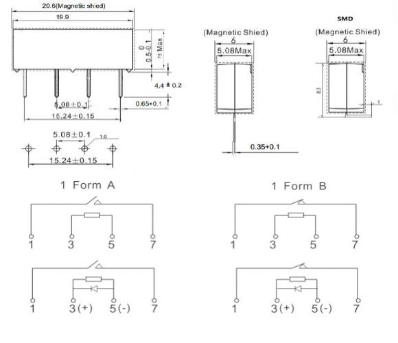
Outline dimension, Wiring diagram, PCB layout (Unit:mm)
Ordering Information
SIP - 1 - A - 05 - D - M - SMD
1 2 3 4 5 6 7
1: Type: SIP
2: Number of Poles: 1-1Pole
3: Contact Arrangement: C From C ; H From A ; B From B
4: Nominal Voltage: 3.5, 12, 24VDC
5: Coil transient suppression: DWith diode; NIL: Standard
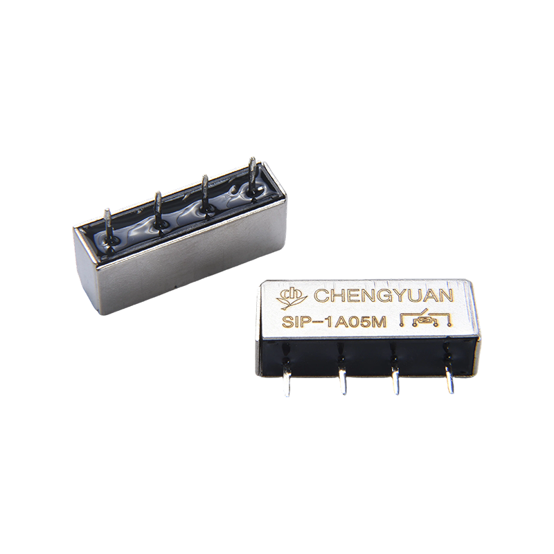
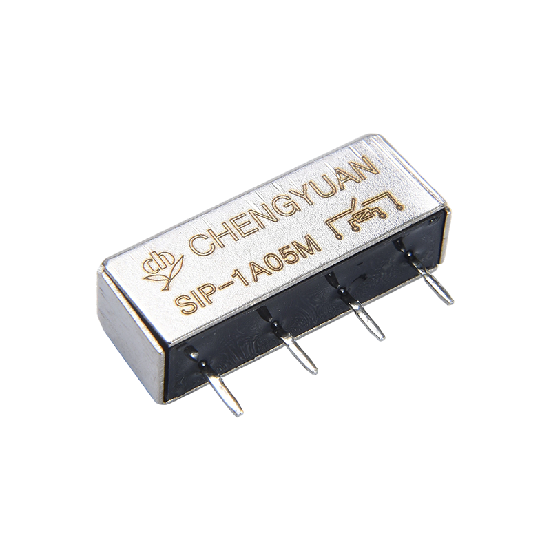
6: With shielding cover: M , NIL Standard
7: SMD, NIL Standard
Disclaimer: The specification is for reference only. Specifications are subject to change without prior notice.
We could not evaluate all the performance and all the parameters for every possible application. Thus, the users should be in the right position to choose
Suitable product for their own application. For sealed relays, after installation and cleaning, please open the ventilation hole in the case before use. If there is any query, please contact Chengyuan for technical services. However, it is the user`s responsibility to determine which product should be used.
 English
 中文简体
中文简体 Español