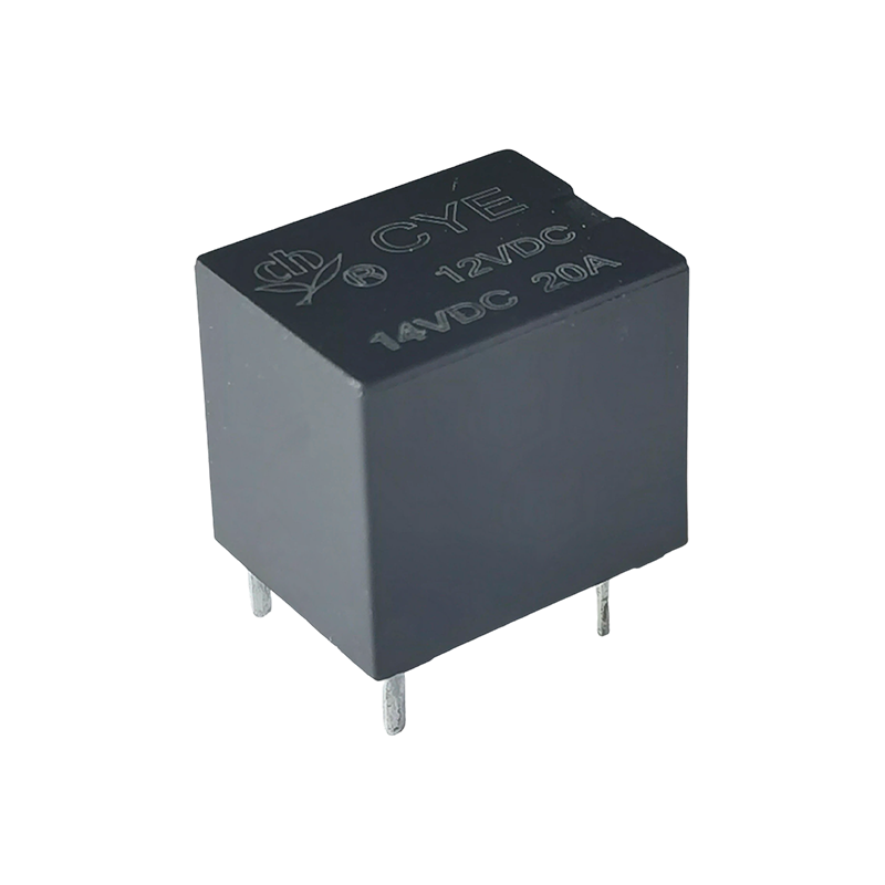
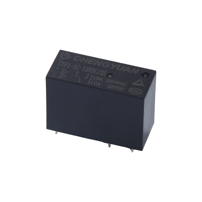
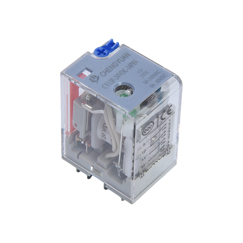
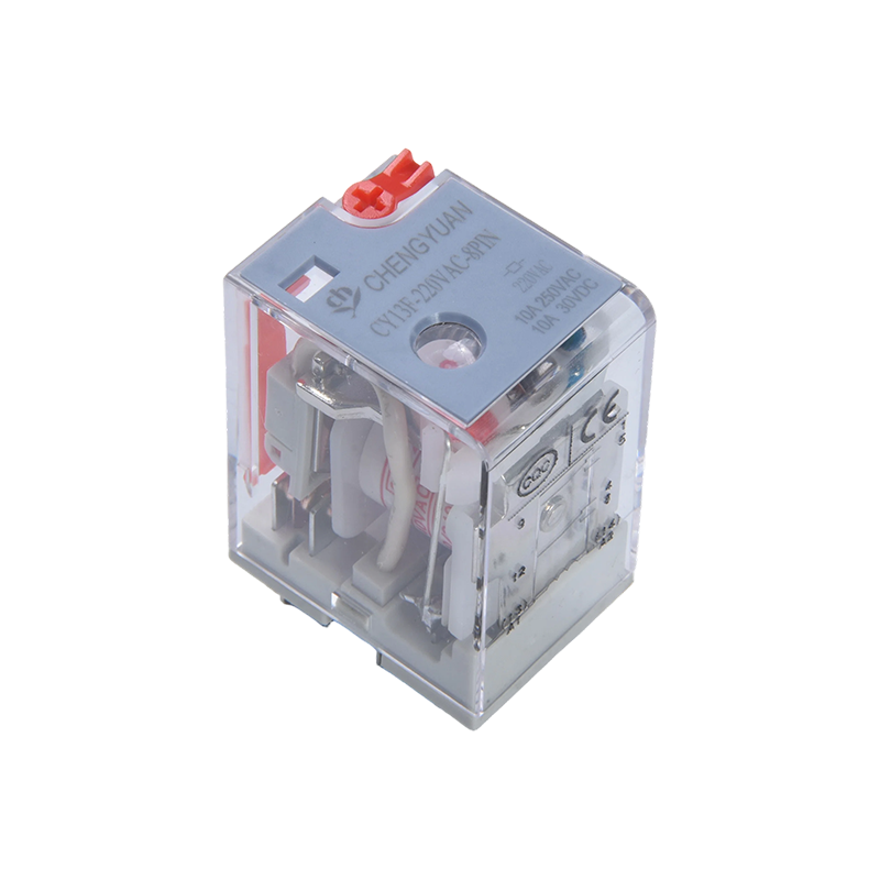
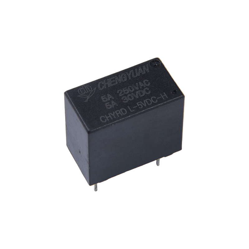
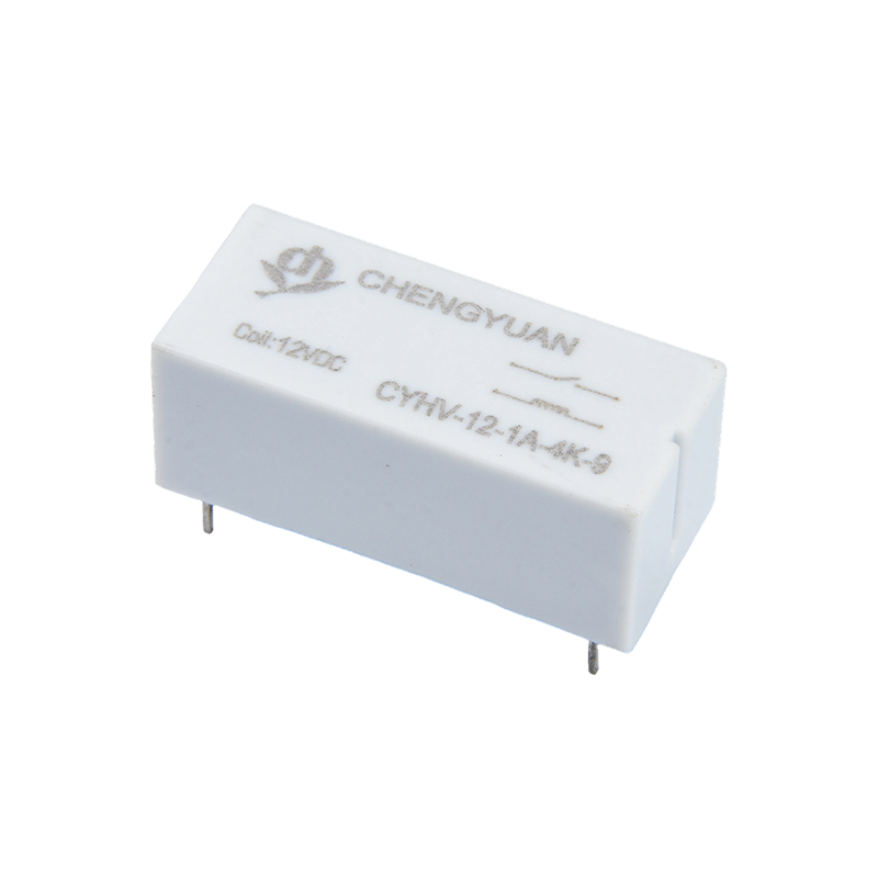
A General purpose electromagnetic relay is an electromechanical switching device that uses a small control signal, typically a low voltage DC or AC coil supply, to open or close a separate, often much larger, load circuit through electromagnetic action rather than direct electrical contact. When current flows through the internal coil, it generates a magnetic field that pulls a movable armature against a spring, and that armature mechanically toggles a set of contacts to complete or break the load circuit. This design gives the relay two properties that make it useful across almost every industry: electrical isolation between the control side and the load side, and the ability to control a heavy load with a very light control signal. The word general purpose specifically distinguishes it from special purpose relays, since a general purpose unit is built to work reliably across a broad range of standard voltages, loads and mounting styles rather than being engineered for one narrow application.
How the Electromagnetic Switching Action Actually Works
The internal mechanism of a general purpose electromagnetic relay follows a consistent sequence regardless of manufacturer or form factor. A coil wound around a magnetic core is energized by the control voltage, which creates a magnetic field strong enough to overcome the tension of a return spring holding the armature in its resting position. As the armature moves, it mechanically drives the relay's contact set, either closing contacts that were open, opening contacts that were closed, or switching a shared contact between two positions depending on the relay's configuration. When the coil is de energized, the spring pulls the armature back to its resting state and the contacts return to their original position.
Basic Operating Sequence
- Control voltage is applied to the coil terminals
- The energized coil generates a magnetic field around its core
- The magnetic field pulls the armature, overcoming the return spring
- Armature movement mechanically switches the load side contacts
- Removing the control voltage lets the spring return the contacts to their resting state
Key Specifications That Define a General Purpose Relay
Selecting or specifying the right relay comes down to a small set of core parameters that appear on essentially every datasheet. Getting these wrong is the most common cause of premature relay failure, since exceeding the coil rating can burn out the coil, and undersizing the contact rating for the connected load can cause contact welding or arcing over time.
Core Specification Reference
| Specification |
What It Defines |
Common Values |
| Coil Voltage |
Control signal needed to energize the relay |
5V, 12V, 24V, 48V, 110V, 220V, AC or DC |
| Contact Rating |
Maximum current and voltage the contacts can safely switch |
3A, 6A, 10A, 16A at 250VAC or 30VDC |
| Contact Configuration |
Arrangement of normally open, normally closed or changeover contacts |
SPDT, DPDT, 3PDT, 4PDT |
| Mounting Style |
How the relay physically installs into a panel or enclosure |
Plug in socket, DIN rail, PCB, screw mount |
These parameters and their test methods are formalized in industry standards such as BS EN 61810-1, which covers general requirements for electromechanical elementary relays, and SAE AS5363, a general specification for electromechanical power controller relays, both referenced in GlobalSpec's electromechanical relay selection guidance.
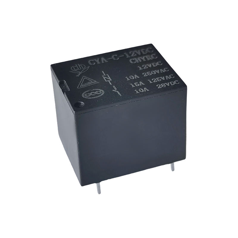
Understanding Contact Configurations
Contact configuration describes how many separate circuits a single relay can switch and in what pattern. A normally open contact stays open when the coil is de energized and closes when energized, while a normally closed contact does the reverse, and a changeover contact combines both in one assembly so the relay can direct power to one of two paths. Multi pole relays extend this same logic across several independent contact sets controlled by a single coil, which is why designs like DPDT, 3PDT and 4PDT exist for applications that need to switch multiple circuits simultaneously from one control signal.
Matching the Relay to the Load Type
The stated contact rating on a datasheet assumes a resistive load, but real world loads are not always resistive, and this distinction significantly affects how a relay should be sized. According to selection guidance published for industrial relay buyers, the load being switched determines roughly 80 percent of the correct relay selection, and different load types require different derating approaches:
- Resistive loads such as heating elements and incandescent lamps generally need a contact rating around 1.25 times the maximum load current
- Inductive loads such as motors, solenoids and transformers should use arc resistant contact materials like AgSnO2 or AgNi, with a contact rating 2 to 3 times the steady state load current to handle inrush current and back EMF
- Capacitive loads such as power supplies and LED drivers need attention to surge current withstand capability to avoid contact welding during startup
Where General Purpose Electromagnetic Relays Are Actually Used
The defining characteristic of a general purpose relay is that it shows up almost everywhere electrical control and load circuits need to be separated. Common application areas include industrial control panels and PLC signal switching, automation equipment, HVAC systems and lighting control, home and commercial appliances, power supply units, and security and office automation equipment. Most low to medium load switching scenarios up to around 12A rated current fall within the practical range of a standard general purpose relay before an application starts to require a heavier duty or special purpose device instead.
Mechanical vs Solid State: Why Electromagnetic Design Still Dominates
General purpose relays are typically built as either electromechanical or solid state devices, and while both switch loads, they are not interchangeable in application. The electromechanical, or electromagnetic, type physically moves a coil driven armature to switch contacts, which makes it a simple, cost effective and easy to inspect solution, though the moving parts are more prone to mechanical wear in very high frequency switching applications. Solid state relays replace the coil and armature with semiconductor switching, which allows a smaller, quieter and often more durable design for high cycle applications, but typically comes at a higher unit cost. For the large majority of standard control, automation and appliance applications where switching frequency is moderate, the electromagnetic type remains the default choice because of its reliability, straightforward diagnostics and lower cost per unit.
Selection Checklist for a General Purpose Electromagnetic Relay
- Confirm the coil voltage and supply type, since an AC coil and a DC coil rated at the same voltage number are not interchangeable
- Match the contact rating to your actual load type, derating for inductive or capacitive loads as needed
- Choose the contact configuration, SPDT, DPDT, 3PDT or 4PDT, based on how many circuits the relay needs to control
- Select a mounting style, plug in socket, DIN rail or PCB, that fits your panel or enclosure design
- Check environmental factors such as temperature, humidity and vibration against the relay's rated operating conditions
A general purpose electromagnetic relay works by using a small coil driven magnetic field to mechanically switch a separate load circuit, giving engineers a reliable, electrically isolated way to control everything from lighting and HVAC equipment to industrial automation and appliance circuits with a single standardized device. Getting the coil voltage, contact rating, contact configuration and load derating right is what separates a relay that lasts for years from one that fails early through coil burnout or contact welding. A properly specified General purpose electromagnetic relay gives control panel builders and equipment designers a dependable, cost effective switching component that fits the broad majority of standard voltage, current and mounting requirements found across industrial and commercial electrical systems.

 English
 中文简体
中文简体 Español