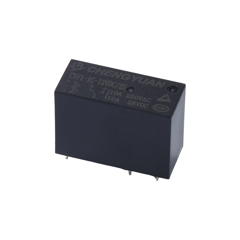
Product Advantages:
• Zero Static Power Consumption: Utilizing the magnetic latching principle, the contact state is maintained without continuous power supply after activation, significantly reducing system standby power consumption.
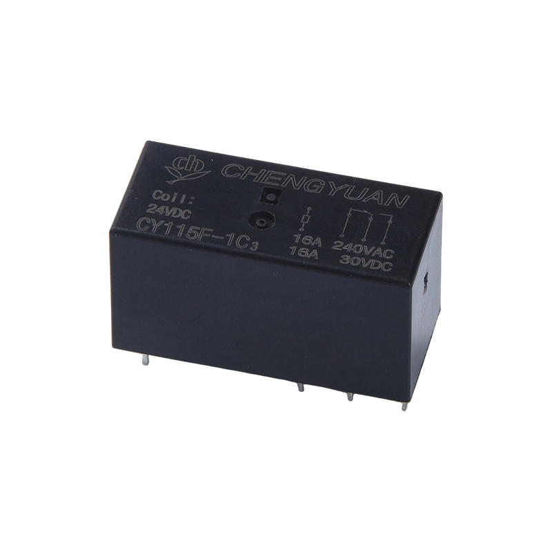
• High Load, Compact Design: Achieves a maximum contact switching capacity of 16A in an ultra-small package, offering high power density and saving PCB space.
• Power-Off State Memory: The contact position remains unchanged after power failure, and the original state is maintained without driving upon power restoration, suitable for backup circuits or safety interlocks.
Features:
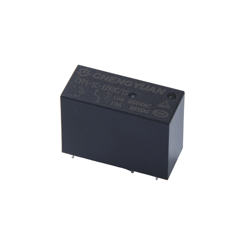
• Maximum 16A contact switching capacity
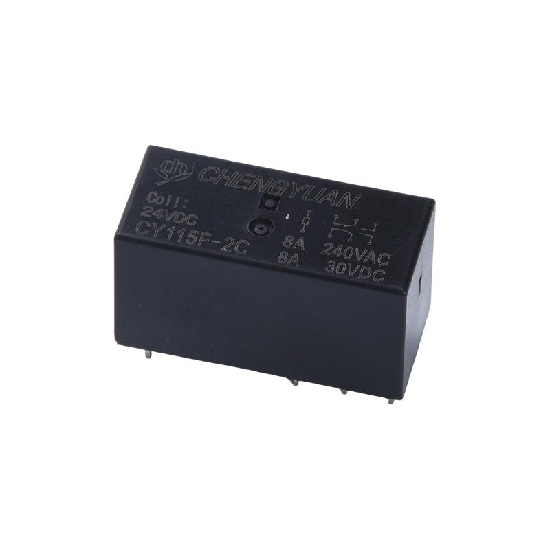
• Available in single-pole and double-pole changeover contact configurations
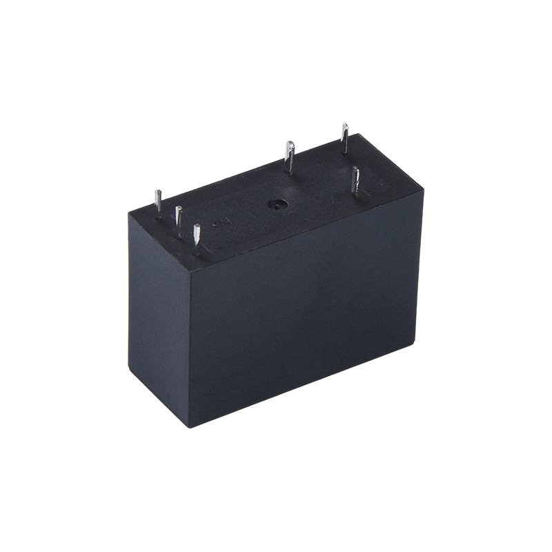
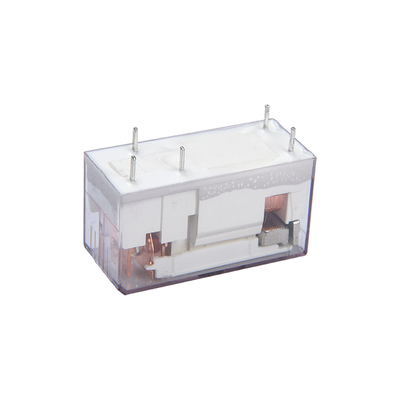
• Ultra-small size, standard PCB pins
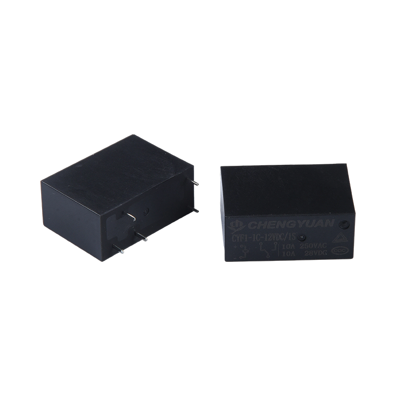
• Available in sealed and flux-proof types
• Environmentally friendly product (ROHS compliant)
• Dimensions: (28.9*12.6*20.6)mm
Main Applications:
• Smart Meters and Energy Management: Used for remote switching control in prepaid meters and smart circuit breakers, achieving low power consumption through magnetic latching.
• Energy-Saving Appliances: Integrated into the main power control of appliances such as air conditioners and water heaters to reduce standby power consumption and meet energy efficiency standards.
• Uninterruptible Power Supplies and Energy Storage: Used in the output switching circuits of UPS and photovoltaic inverters, ensuring system continuity by maintaining the state during power outages.
• Safety and Fire Protection Systems: Used in alarm systems and emergency lighting control circuits to ensure reliable switch status during sudden power failures.
Contact Parameters
|
Contact Configuration
|
1A/1C
|
2A/2C
|
|
Contact Resistance
|
< 50mΩ (1A 6VDC)
|
|
Contact Material
|
AgSnO₂,AgCdO
|
|
Contact Load (Resistive)
|
20A 250VAC
16A 250VAC/28VDC
10A 250VAC/28VDC
|
8A 250VAC
5A 277VAC/28VDC
|
|
Maximum Switching Voltage
|
250VAC / 28VDC
|
|
Maximum Switching Current
|
20A/16A/10A
|
8A/5A
|
|
Maximum Switching Power
|
5000VA/480W
|
1200VA/150W
|
|
Mechanical Durability
|
1×10⁷ cycles
|
|
Electrical Durability
|
1×10⁵ cycles
|
Coil Parameters
|
Rated Coil Power
-
|
Single Coil 540mW
|
|
Dual Coil ≦1W (Power varies by specification)
|
|
Coil Temperature Rise
|
26°C (47°F) at rated voltage
|
|
Maximum Temperature
|
130°C (266°F)
|
Coil Specification Table
|
Rated Voltage (VDC)
|
Set/Reset Voltage (VDC)
|
Pulse Width (ms)
|
Dual Coil Resistance (Ω±10%)
|
Single Coil Resistance (Ω±10%)
|
|
Coil 1
|
Coil 2
|
|
3
|
≤2.40
|
≥50
|
12.5
|
10.6
|
12.5
|
|
5
|
≤4.00
|
≥50
|
37
|
33
|
42
|
|
12
|
≤9.60
|
≥50
|
200
|
169
|
267
|
|
24
|
≤19.2
|
≥50
|
800
|
680
|
1067
|
|
48
|
≤38.4
|
≥50
|
2780
|
2315
|
4267
|
Performance Parameters
|
Insulation Resistance
|
100MΩ (500VDC)
|
|
Dielectric Withstand Voltage
|
Between Contact and Coil
|
5000VAC for 1min
|
|
Between Open Contacts
|
750VAC for 1min
|
|
Operate Time (at rated voltage)
|
≤10ms
|
|
Release Time (at rated voltage)
|
≤5ms
|
|
Shock
|
Stability
|
100m/s² (10g)
|
|
Strength
|
1000m/s² (100g)
|
|
Vibration
|
10Hz~55Hz, 1.5mm double amplitude
|
|
Humidity
|
35%~85% RH
|
|
Temperature Range
|
-40°C ~ 85°C
|
|
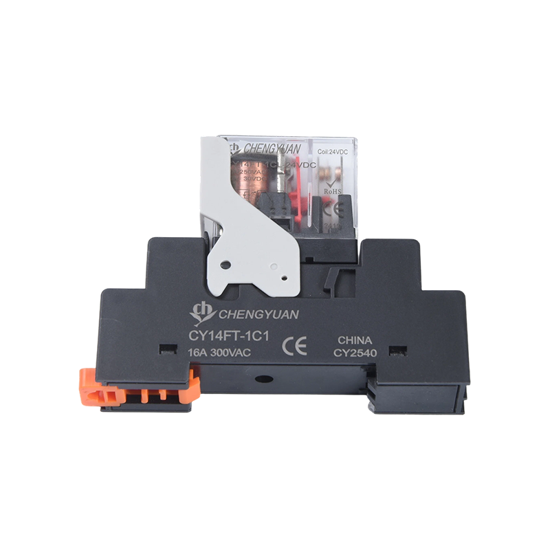
Terminal Type
|
PCB type
|
|
Weight
|
Approximately 10g
|
|
Packaging Type
|
Plastic-sealed type, solder-resistant type
|
Safety Certifications
|
CQC
|
1A/1C
|
16A 250VAC
16A 28VDC10A
|
|
1A/1C
|
10 250VAC
10 28VDC
|
|
2A/2C
|
8A 250VAC
8A 28VDC
|
|
TUV
|
1A/1C
|
16A250VAC cos phi=1
16A 28/R=0ms
|
|
1A/1C
|
10 250VAC
10 28VDC
|
|
2A/2C
|
8A250VAC cos phi=1
8A 28/R=0ms
|
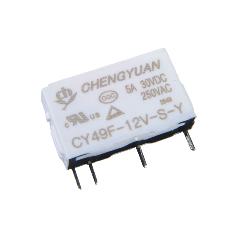
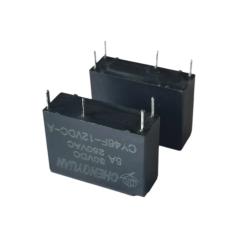
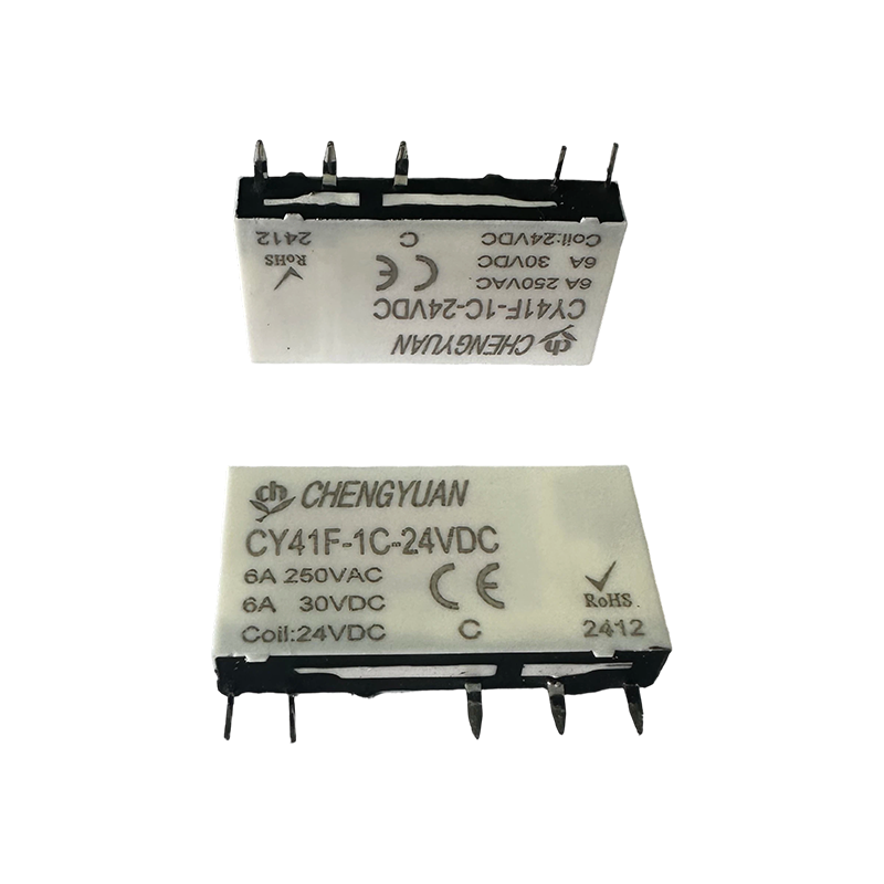
Ordering mark example
Relay model CYF
Coil voltage 5 6 9 12 18 24 48 VDC
Contact form 1A: one group of normally open, 1C: one group of conversion, 2A: two groups of normally open, 2C two groups of conversion
Coil form 1S: single coil 2S: double coil
Contact material T: AgSnO2, None: AgCdO
Remarks: (1) In an environment containing harmful gases such as H2S, SO2, NO2, etc., it is recommended to use plastic-sealed products, and please conduct tests and confirmation in actual use; when overall cleaning is not required, it is recommended
It is recommended to give priority to flux-resistant products;
- This product is an environmentally friendly product. Please mark the corresponding feature number when ordering, where (551) indicates RoHS compliance (contacts contain cadmium), and (555) indicates RoHS compliance (contacts do not contain cadmium).
Wiring diagram, mounting hole size unit: mm
(1) Dimensional tolerances are not specified for some external dimensions of the product. When the external dimensions are ≤1mm, the tolerance is ±0.2mm; when the external dimensions are between 1~5mm, the tolerance is ±0.3mm.
When the overall size is >5mm, the tolerance is ±0.4mm;
(2) The mounting hole dimensions without dimensional tolerance are ±0.1mm.
Things to note:
- The factory state of the magnetic latching relay is the reset state, but due to factors such as impact during transportation or installation of the relay, it may change to the action state. Therefore, when using (power supply
When connected, please reset it to the action state or reset state as needed.
- In order to ensure that the magnetic latching relay acts or resets, the excitation voltage applied to the coil must reach the rated voltage, and the pulse width must be greater than 5 times the action or reset time. Do not
When applying voltage to the action and reset coils, do not apply voltage to the coils for a long time (more than 1 minute).
- During product transportation, storage, and application, please keep the product away from strong magnetic fields to avoid changes in operating voltage and reset voltage.
 English
 中文简体
中文简体 Español