Open a motor starter drawing and you will usually see the same pattern: a rectangle marked A1 and A2 near the top of the sheet, three pairs of short parallel lines below it, and one or two small contacts off to the side with a diagonal stroke through the arm. That is an electrical contactor symbol, and it is really a group of symbols rather than a single picture. The rectangle is the operating coil. Each pair of lines is one contact that the coil drives. The diagonal stroke marks a contact that is closed while the coil is off. Once you separate the coil from the contacts, the numbering beside each symbol, the cross references between sheets, and the part you eventually order all start to line up.
The Coil and the Contacts Are Drawn Separately
IEC style schematics place the coil wherever the device physically sits in the panel and place each contact wherever its wiring lands. A three pole contactor therefore produces four symbols on the sheet even though it is one component. The reference designator keeps them together: KM1 for the contactor on every symbol, or K1 and KA when the device is treated as a relay.
Three drawing conventions matter more than the shape of the box:
- Contacts are drawn in the de-energized state. A normally closed contact appears closed on the sheet, even though it opens as soon as the coil is energized.
- Normally open contacts are shown as a gap between the fixed and the moving arm. Normally closed contacts carry a diagonal stroke or a small perpendicular bar, depending on the standard.
- Main current carrying poles and auxiliary poles use the same contact symbol. What separates them is the numbering and the position in the circuit, not the graphic.
That last point is where most reading errors begin. A 16 A main pole and a 5 A auxiliary contact look identical on the drawing. Only the numbers and the connected load tell you which one is which.
IEC 60617 and NEMA Style Reach the Same Meaning
A drawing set following IEC 60617, BS 3939 or EN 60617 uses a compact set of contact symbols with reference designators and cross references between sheets. Normally closed contacts take a diagonal stroke through the moving arm, coils are rectangles, and mechanically linked contacts may carry a dashed line. North American drawings in NEMA or IEEE 315 style often place contacts in a vertical column beside the coil, use a straight line for a normally open contact and a slash for a normally closed one, and keep the ladder format that electricians read from left to right.
Both traditions use the same contact symbols for contactors and relays. The pictogram does not separate a contactor from a relay. What separates them is the standard the device is tested to, IEC 60947-4-1 for contactors and IEC 61810 for relays, the current the contacts are expected to break, and the designator printed beside the symbol. A solid state contactor changes the picture more visibly: the contact block gives way to a rectangle containing a semiconductor symbol, and mechanical linkage lines disappear because nothing moves.
When a drawing travels between regions, ask which standard the originator worked to before you redraw anything. A contact that reads as normally closed in one house style can be interpreted as a transfer contact in another.
What the Numbers Beside the Symbols Mean
IEC 60947-5-1 gives contactor and relay contacts a two digit terminal numbering system that survives translation. The first digit identifies the pole position, the second identifies the function. A contact marked 13-14 is an auxiliary normally open contact, while 21-22 is an auxiliary normally closed contact on the same pole position. Coils are marked A1 and A2, and the coil circuit is normally drawn with the protection or suppression device that sits across it.
Terminal numbering commonly used with IEC style contactor and relay symbols.
| Symbol on the drawing |
Typical terminals |
State with the coil de-energized |
Typical use |
| Contactor or relay coil |
A1, A2 |
No contact action |
Control circuit, often with a diode or RC suppressor |
| Main normally open pole |
1-2, 3-4, 5-6 |
Open |
Motor supply and resistive loads |
| Main normally closed pole |
Same pairs with a mirrored arm |
Closed |
Braking circuits and safety drop out |
| Auxiliary normally open |
13-14, 23-24, 33-34 |
Open |
Seal in circuits and PLC feedback |
| Auxiliary normally closed |
21-22, 31-32, 41-42 |
Closed |
Interlocks and stop circuits |
| Overload trip contact |
95-96 |
Closed |
Thermal overload relay output |
| Solid state contactor |
Input and output terminals |
Depends on the control signal |
Frequent switching without arcing |
Two habits keep the table useful in practice. Read the tens digit first, because a contact numbered in the forties belongs to the fourth pole and not to a second device. Then check the state convention against the machine sequence, since every contact on the sheet is drawn as if the coil were off.
Latching devices break that convention in a useful way. A magnetic latching relay may be drawn with two coils for set and reset, or with a latch mark inside the coil rectangle, and its contacts stay where they were left after power is removed. The drawing then has to state the assumed state at power up, because the de-energized rule no longer predicts the contact position.
 CYF1-S Relay,Magnetic latching relay,14F latching relay,10A Magnetic Latching Relay.In control scenarios requiring low power consumption and state memory, the CYF1-S Relay, as a magnetic latching relay, offers significant advantages with its unique bi...View Product →
Look Alike Symbols and Where Drawings Go Wrong
- The overload trip contact at 95-96 often sits next to the contactor coil and is mistaken for an auxiliary normally closed contact at 21-22. Only 95-96 opens on a thermal trip, not when the coil is energized.
- Reversing and star delta starters draw main contacts with mirrored arms. A mirrored main pole is usually a normally closed pole used for interlocking, not a second normally open pole.
- Timer contacts carry a half circle with an arrow. The arrow direction tells you whether the delay applies on energizing or on release, and ignoring it inverts the sequence.
- A diode, RC network or varistor drawn in parallel with the coil is a suppression circuit, not a second coil. It sits across A1 and A2 and has no contacts of its own.
- A reed relay uses the same contact symbols as an electromagnetic relay, although the coil symbol is sometimes drawn around a reed capsule. The electrical meaning is unchanged.
From Symbol to the Part in the Enclosure
Once a drawing is read, the order list writes itself: pole count, contact form, coil voltage and coil type, contact rating, and mounting. A schematic showing two changeover contacts driven by one 24 VDC coil describes a double pole double throw relay with a 24 VDC coil. A drawing showing a single changeover contact switching a 12 A inductive load at 250 VAC describes a single pole double throw relay rated for that load and fitted with a contact material suited to inductive duty.
Current matters more than the picture. Relays and contactors share contact symbols, but a device rated for 10 A resistive load will not carry the same current into a motor load, and the derating curves in the datasheet decide the real limit. Bring the drawing, the load type and the ambient temperature to the supplier rather than the symbol alone.
 CY13F Relay ,Power Relay DPDT,JQX-13F ,industrial power relay,DPDT/2Z,MY2 LY2.8PINThe CY13F relay is a versatile general-purpose relay with multiple contact options. Compared to other relays in the same category, it offers the advantage of flexible ...View Product →
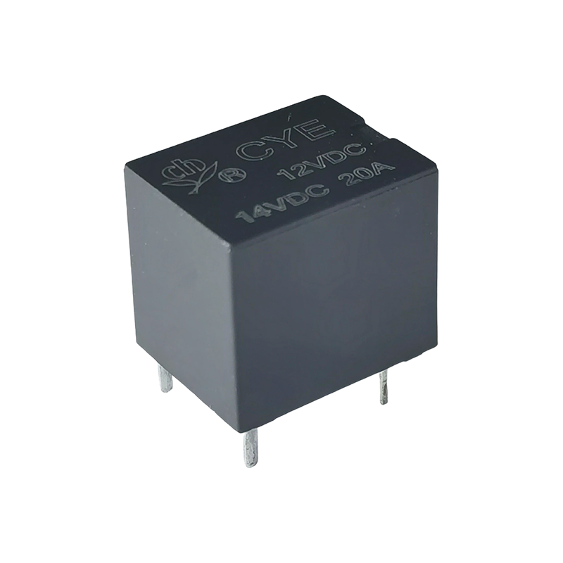
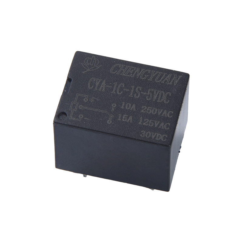
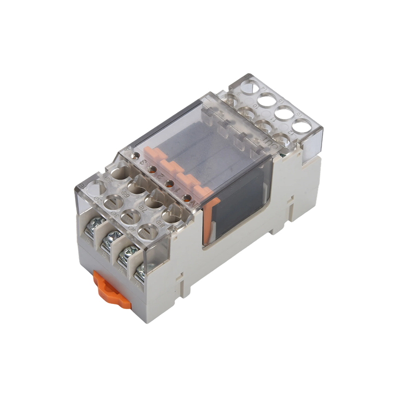
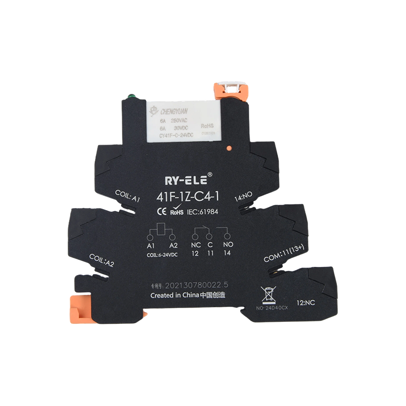
Ningbo Chengyuan Chuangke Electronics has built relays in Yinzhou, Ningbo since 1996, and its catalogue covers four families that match most contact arrangements found on a control drawing: general purpose electromagnetic relays, reed relays, magnetic latching relays and rail mounted industrial control modules. Panels that follow a drawing with rail mounted devices are usually built from modules rather than bare relays.
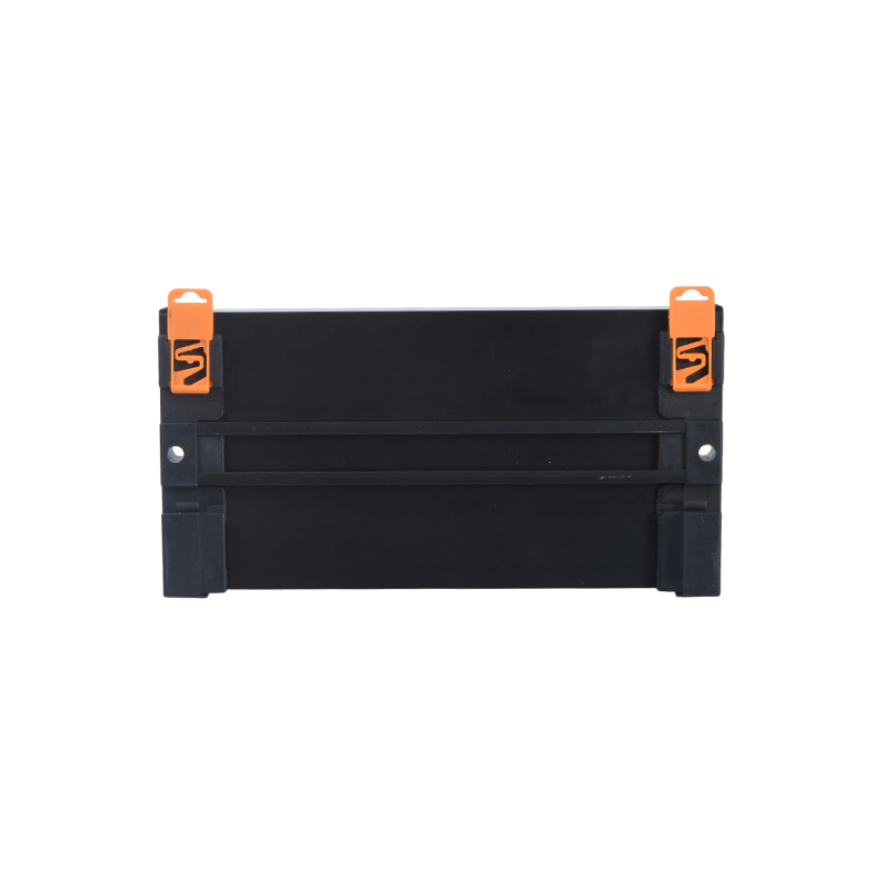 MCYF1 Relay Module ,14F Rail Relay Module,14F 10A Industrial connection module.In industrial control system rail-mounting applications, the MCYF1 Relay Module series offers an efficient modular solution based on magnetic latching relays. Compared...View Product →
For background on how a simple changeover contact is actually built and switched, the explanation of what a general purpose electromagnetic relay does is a useful companion to the symbol chart, and the company profile shows which relay families sit behind the designators on your drawing.
Next time a contactor symbol slows you down, work the drawing in one direction only. Find the coil and its A1 and A2 terminals, list every contact that shares the designator, read the numbers to establish pole and function, then check the de-energized state against the sequence the machine has to run. The symbol set tells you the switching logic, and the datasheet tells you whether the part survives the current. Match both before the order is released.

 English
 中文简体
 Español