A control cabinet failed a routine factory test last month. The main breaker tripped as designed, but the relay coil on the downstream control board had already burned. The problem was not a missing protection device. It was a protection plan that stopped at the branch circuit and ignored the control layer.
Effective electrical circuit protection is a layered system, not a single component. It begins with branch-circuit devices that clear faults, continues through control and isolation components that manage abnormal conditions, and ends with the loads that must survive or shut down safely. The sections below explain what each layer does, how to choose devices, and where relays and control modules fit.
What Electrical Circuit Protection Really Covers
Electrical circuit protection is often reduced to circuit breakers and fuses. Those devices matter, but they cover only part of the risk. A complete protection strategy addresses four fault categories:
- Overcurrent and short circuit. Excessive current from overload, phase-to-phase contact, or ground fault can overheat conductors and destroy components within milliseconds.
- Overvoltage and surge. Switching transients, lightning, and inductive kickback can exceed insulation ratings and damage control electronics.
- Undervoltage and phase loss. Motors and relays may chatter, overheat, or fail to start when supply voltage drops or one phase disappears.
- Residual current and earth leakage. Small leakage currents can indicate insulation failure and create shock or fire hazards.
Each category needs the right device at the right point in the circuit. A breaker at the panel cannot protect a sensitive relay coil from a transient that occurs downstream. A surge protector at the service entrance cannot clear a short circuit inside a control cabinet. Protection works only when devices are coordinated across layers.
Core Devices and What Each One Does
Different protection devices respond to different faults. The table below summarizes common components and the data you need before selecting them.
Comparison of common electrical circuit protection devices and their primary selection data.
| Device |
Primary role |
Typical placement |
Key selection data |
| Miniature circuit breaker (MCB) |
Clear overloads and short circuits |
Branch circuit or feeder |
Rated current, trip curve, breaking capacity |
| Fuse |
Clear short circuits with high speed |
Semiconductor, transformer, or control circuit |
Ampere rating, I2t, voltage rating, interrupting rating |
| Residual current device (RCD or RCBO) |
Detect earth leakage and disconnect |
Socket circuits, wet areas, equipment feeders |
Sensitivity, trip time, type (AC, A, B) |
| Surge protection device (SPD) |
Limit transient overvoltage |
Service entrance or sub-panel |
Voltage protection level, surge current, response time |
| Overload relay |
Protect motors from sustained overcurrent |
Motor starter or contactor |
Setting range, trip class, phase loss sensitivity |
| Control relay or module |
Isolate, switch, and monitor control signals |
Control panel or PCB assembly |
Coil voltage, contact rating, mechanical life, mounting |
A common mistake is treating these devices as interchangeable. A relay can switch a control signal, but it cannot replace a breaker for branch-circuit protection. An SPD can absorb a surge, but it will not clear a short circuit. Each device has a defined job, and the system fails when one device is asked to do another device's work.
Where Relays and Control Modules Fit in Protection
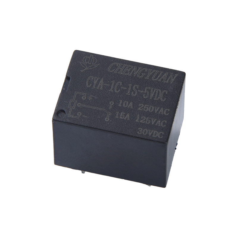
 CYF1 Relay ,SPSP Relay,JQX-14F,10A 250VAC Relay,16A Relay ,5PIN PCB Relay.PCB 0.54W Relay.The CYF1 Relay is a high-performance printed circuit board (PCB) mounted electromagnetic relay, also known as the SPSP Relay, JQX-14F Relay, or 14F power relay. This p...View Product →
Relays are not primary protective devices, but they play a critical role in protection systems. They detect abnormal conditions through auxiliary contacts, isolate control circuits, and switch alarms or shutdown signals. In motor control, an overload relay uses a current sensing element and a set of contacts to open the contactor coil when current exceeds a set threshold. In monitoring circuits, a voltage relay can trip when supply rises or falls outside a safe window.
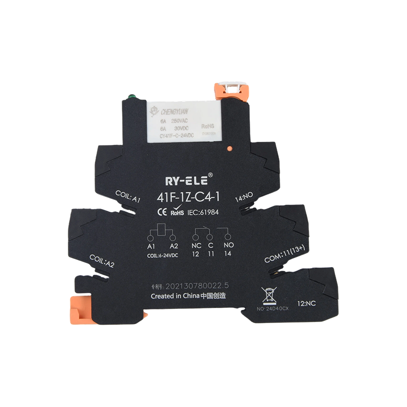
Industrial control modules take this further by combining relays, sockets, indicators, and sometimes fuses or surge suppression into a DIN-rail assembly. These modules simplify wiring and reduce the chance of loose connections, which are a common source of intermittent faults. For panel builders, a pre-assembled module can shorten assembly time and make replacement more predictable.
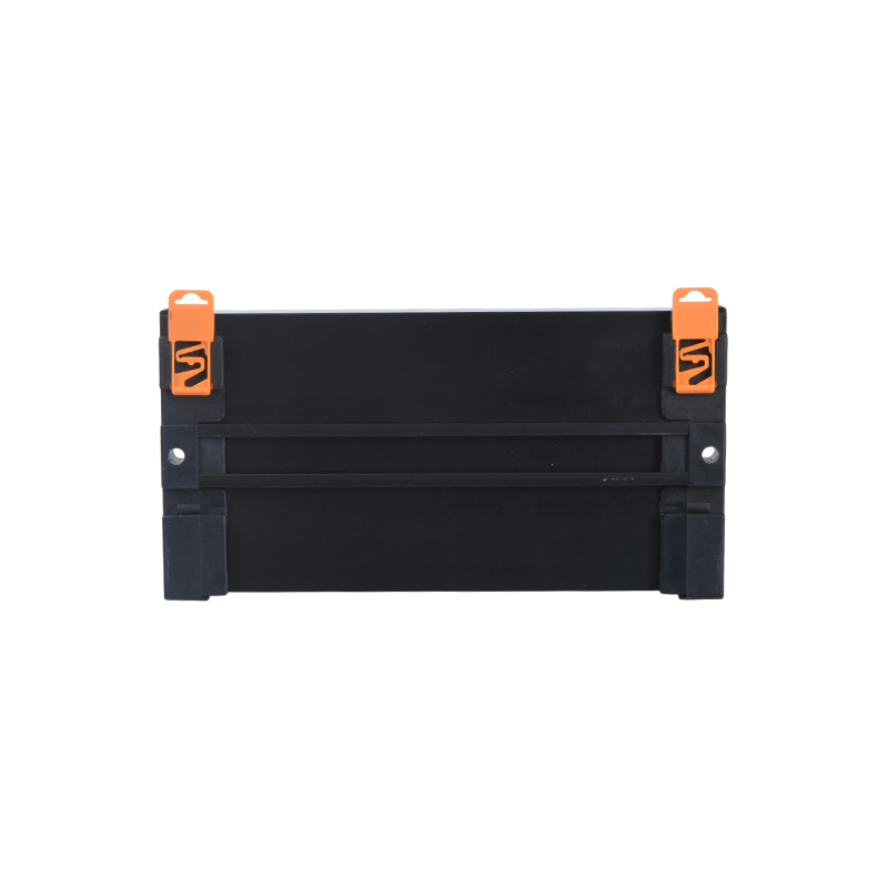 MCYF1 Relay Module ,14F Rail Relay Module,14F 10A Industrial connection module.In industrial control system rail-mounting applications, the MCYF1 Relay Module series offers an efficient modular solution based on magnetic latching relays. Compared...View Product →
When specifying a relay for a protection or control function, look beyond the coil voltage. Contact rating, expected switching cycles, and the ability to withstand inrush current matter just as much. A relay rated for 10 A resistive load may not survive a 10 A motor load with high inrush. Check the manufacturer's derating curves and test data. You can review our relay manufacturing background on the about page to see how these ratings are developed.
Selection Criteria That Reduce Risk
Protection devices are often selected on price and ampere rating alone. That approach creates hidden risks. Use the following criteria to compare options and document your choices.
- System voltage and insulation coordination. Confirm the device rating is suitable for the highest continuous voltage and the impulse voltage expected at that location. A 250 VAC rated relay should not be used on a 277 VAC circuit without verification.
- Continuous current and ambient temperature. Current ratings are usually given at a reference temperature, often 20 or 25 degrees Celsius. At 60 degrees Celsius inside a panel, a device may need significant derating.
- Breaking capacity and fault level. At the point of installation, calculate the prospective short-circuit current. A device with insufficient breaking capacity may fail to clear the fault safely.
- Response time and coordination. Fast devices are not always better. A fuse may clear a fault before a downstream relay can react, but it may also nuisance trip on motor starting. Compare time current curves.
- Environment and ingress protection. Dust, moisture, corrosive gas, and vibration affect device life. Choose enclosures and sealed components that match the actual environment, not the cleanest possible condition.
- Certification and traceability. For export markets, check UL, CE, or other required marks. Ask for lot traceability and test reports. Missing documentation can delay customs clearance and create liability.
Write these values into a selection table for each project. When a device fails later, the table tells you whether the fault came from a wrong rating, an installation error, or an unexpected load change.
Coordination and Selectivity
 CYF1-S Relay,Magnetic latching relay,14F latching relay,10A Magnetic Latching Relay.In control scenarios requiring low power consumption and state memory, the CYF1-S Relay, as a magnetic latching relay, offers significant advantages with its unique bi...View Product →
Coordination means that the device closest to the fault clears it without disturbing upstream devices. Selectivity means that an upstream breaker does not trip when a downstream fault occurs. Both depend on time current curves, energy let-through, and the impedance between devices. In a well coordinated system, a fault in one control panel stops that panel only. In a poorly coordinated system, the main breaker trips and shuts down the entire line.
Relays and control modules influence coordination in two ways. First, their coil and contact characteristics determine how quickly a control circuit responds. Second, their holding current affects the total load seen by the upstream breaker. Magnetic latching relays, for example, hold their state without continuous coil power. That reduces heat and steady-state load, which can help when a control panel is already near its thermal limit.
Test coordination during commissioning, not after a failure. Use a temporary adjustable load or a secondary injection test set to confirm that the intended device trips first. Record the results and keep them with the panel documentation.
Common Mistakes and Procurement Risks
Most protection failures come from decisions made before installation. Watch for these recurring problems:
- Using a relay as a breaker. Relays switch and isolate, but they do not have the breaking capacity to clear a short circuit. Relying on relay contacts for branch protection creates a fire risk.
- Ignoring ambient temperature. A device rated 10 A at 25 degrees Celsius may carry only 7 A at 60 degrees Celsius. Panels without ventilation often run hotter than expected.
- Mixing devices from different coordination tables. Selectivity data is valid only for tested combinations. Substituting a similar breaker or fuse can void the coordination study.
- Buying on price alone. Low-cost components may have optimistic ratings, weak terminal plating, or inconsistent trip points. In critical systems, the cost of a nuisance trip or a failed trip is far higher than the price difference.
- Forgetting spare parts and documentation. A protection system is only as good as its maintenance plan. Without spare relays, fuses, and wiring diagrams, a simple fault can become a long downtime event.
Ask suppliers for test data, certificates, and sample evaluation units. If a supplier cannot provide basic ratings or traceability, treat that as a warning sign. You can contact our team for relay and module selection support if you need application specific guidance.
Testing, Maintenance, and Replacement
Protection devices are mechanical and electrical components. They age, drift, and fail. A practical maintenance program includes:
- Visual inspection for discoloration, corrosion, loose terminals, and moisture.
- Thermal imaging of breakers, fuses, and relay terminals under normal load.
- Trip testing of RCDs and RCBOs at the recommended interval, usually every six months for critical circuits.
- Functional testing of overload relays and control modules during scheduled shutdowns.
- Replacement of devices after a fault, even if they still appear to work. A breaker or relay that has interrupted a high fault current may have internal damage that is not visible.
Keep a spare parts list that matches the original ratings and coordination study. Do not substitute a different trip curve or breaking capacity without reviewing the whole system. A like-for-like replacement is the fastest and safest path.
Key Takeaways
Electrical circuit protection is a system, not a shopping list. Start with a fault study, choose devices that match the available fault current and environmental conditions, and verify coordination before the panel goes into service. Use relays and control modules for isolation, monitoring, and control, but never as a substitute for branch-circuit protective devices.
When you document ratings, test results, and replacement parts, you turn protection from a box of components into a reliable, maintainable part of the facility. That approach reduces downtime, prevents damage, and keeps people safe.

 English
 中文简体
 Español