DOL Starter Motor Guide: Wiring, Current Ratings and Control Relay SelectionDOL Starter Motor Guide: Wiring, Current Ratings and Control Relay SelectionDOL Starter Motor Guide: Wiring, Current Ratings and Control Relay SelectionDOL Starter Motor Guide: Wiring, Current Ratings and Control Relay SelectionDOL Starter Motor Guide: Wiring, Current Ratings and Control Relay SelectionDOL Starter Motor Guide: Wiring, Current Ratings and Control Relay SelectionDOL Starter Motor Guide: Wiring, Current Ratings and Control Relay SelectionDOL Starter Motor Guide: Wiring, Current Ratings and Control Relay SelectionDOL Starter Motor Guide: Wiring, Current Ratings and Control Relay SelectionDOL Starter Motor Guide: Wiring, Current Ratings and Control Relay SelectionDOL Starter Motor Guide: Wiring, Current Ratings and Control Relay SelectionDOL Starter Motor Guide: Wiring, Current Ratings and Control Relay SelectionDOL Starter Motor Guide: Wiring, Current Ratings and Control Relay SelectionDOL Starter Motor Guide: Wiring, Current Ratings and Control Relay SelectionDOL Starter Motor Guide: Wiring, Current Ratings and Control Relay SelectionDOL Starter Motor Guide: Wiring, Current Ratings and Control Relay Selection
News
Home / News / Industry News / DOL Starter Motor Guide: Wiring, Current Ratings and Control Relay Selection
DOL Starter Motor Guide: Wiring, Current Ratings and Control Relay Selection
A 7.5 kW borewell pump trips the feeder breaker for the third time this month. The windings test fine, the insulation reads clean, and the no-load current sits where it should. The fault is in the starter panel: an undersized contactor, an overload dialled down too far, or a direct on line arrangement applied to a load that never should have had one.
For most three phase squirrel cage motors between 0.37 kW and 15 kW, a DOL starter motor circuit is still the simplest, cheapest and most serviceable answer, provided two conditions hold. The supply must be able to absorb the inrush without dragging terminal voltage below the contactor hold-in threshold, and the driven load must tolerate a hard, uncontrolled start. Everything below is about testing those two conditions before you order parts.
What a DOL Starter Does in the First Two Seconds
A direct on line starter does exactly one thing: it applies full line voltage to the stator through a contactor. There is no reduced voltage stage, no transformer tap, no semiconductor ramp. The instant the coil energises, the motor terminals see 380 V or 415 V, and the rotor accelerates as quickly as the load inertia allows.
That is not a defect. At the moment of switching, slip equals one, and the cage rotor behaves like a short circuited transformer secondary. The current is correspondingly large. An IEC rated motor typically draws locked rotor current of six to eight times full load current, at a power factor near 0.3, which means most of that surge is reactive and does real damage to line voltage rather than to the motor itself.
The torque side of the equation is friendlier. At full voltage the starting torque usually lands between 1.5 and 2.5 times full load torque, depending on rotor design. That is the trade a DOL starter makes: generous torque, punishing current.
Practically, that means a direct on line starter is the right call when the supply can carry the surge and the load does not need a gentle ramp. It is the wrong call when both of those are false, and it is a coin flip when only one is.
Inside the Panel: Which Parts Fail First
Most DOL failures never reach the motor. One component gives up first and takes a neighbouring circuit with it.
Contactor: switches the motor on and off under full voltage. Rated for AC-3 duty, with contact current capacity covering both starting and running current.
Thermal overload relay: trips on sustained excess current, not on the normal starting surge. Its trip class decides how many seconds of six times current it will tolerate.
MCB or fuse: handles short circuit protection, which is a different job from overload protection. Coordination between the two is the most commonly missed check.
Start and stop push buttons: cheap parts with the highest switching count, and the first to oxidise in dusty or humid rooms.
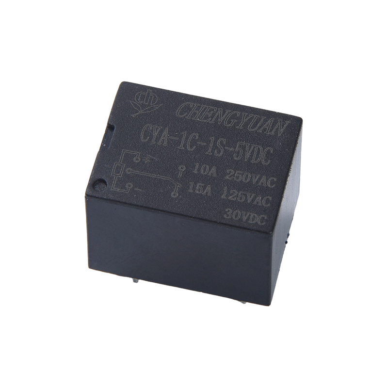
Control relay: interfaces remote signals, timers and interlocks to the contactor coil. As panels grow, this is where intermittent faults concentrate.
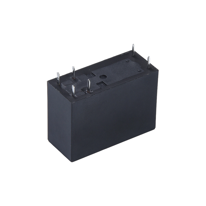
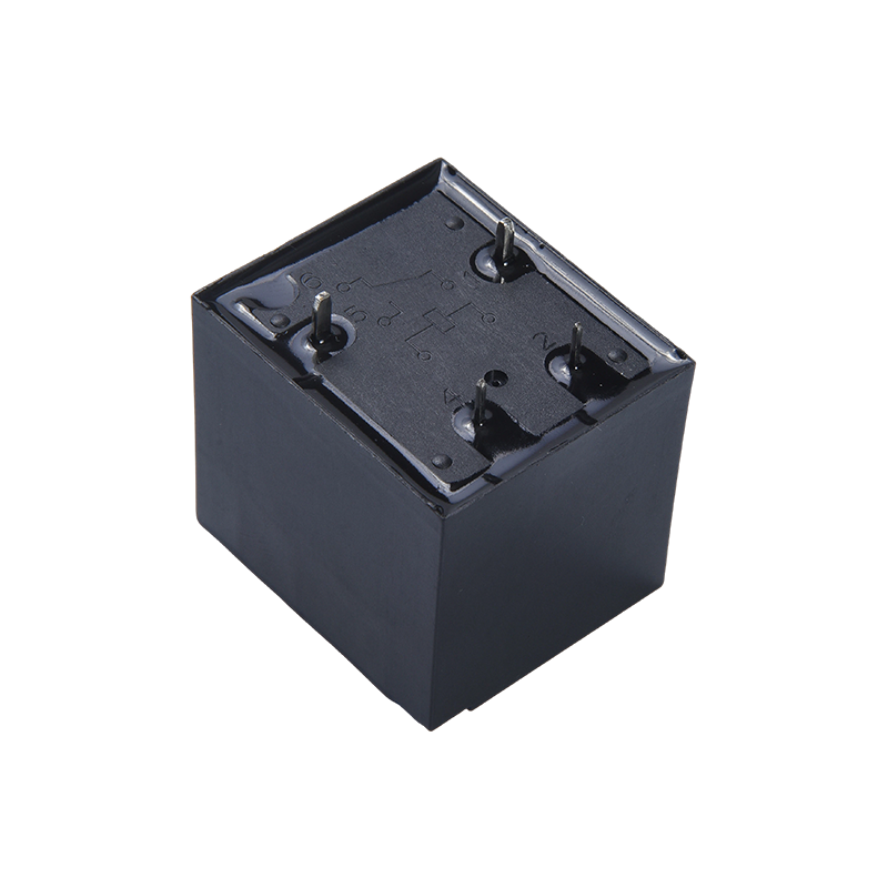
The control circuit is the underrated half of a starter. A small intermediate relay or a general purpose electromagnetic relay lets a thin control cable drive a heavy contactor coil, and the relay contacts take the switching wear instead of the coil.
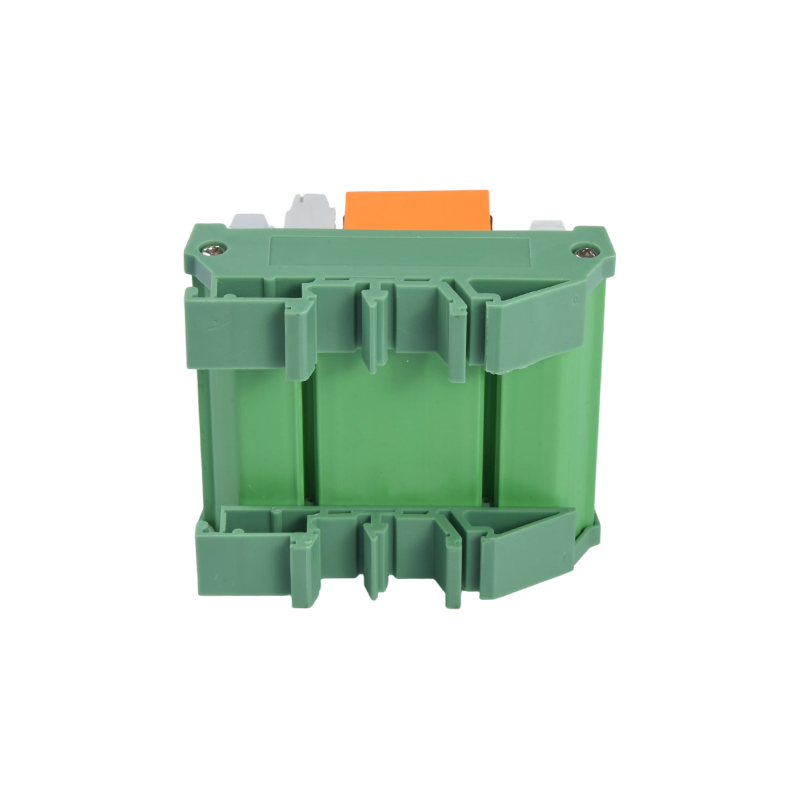
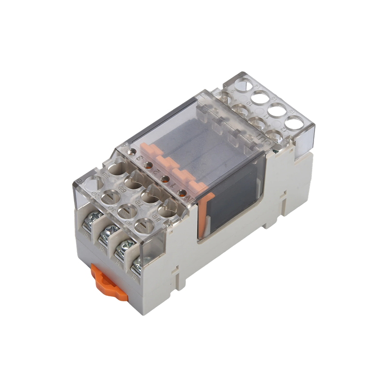
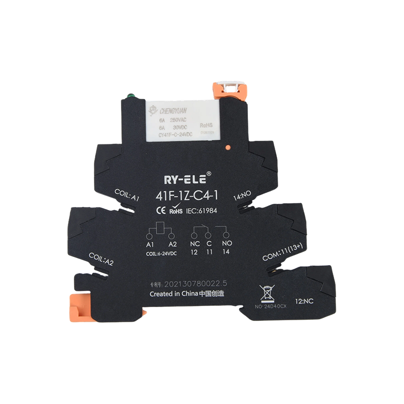
Coil voltage, contact rating and whether the relay offers a manual test lever all matter more than the datasheet headline. In panels with several motors, DIN rail mounted modules remove the need to wire individual relay bases and make replacement a ten second job.
The table below summarises what each part is actually being asked to do, and where it tends to go wrong.
Component roles in a direct on line starter and the failure modes seen most often in the field
Component
Primary function
Common failure mode
Check before ordering
Contactor
Switch the motor main circuit
Contact erosion, chatter on low voltage
AC-3 rating and coil voltage
Thermal overload relay
Detect sustained overload
Set too low, nuisance trip on start
Trip class and motor full load current
MCB or fuse
Clear short circuits
Curve mismatch with starting surge
Breaking capacity and discrimination
Push buttons
Manual run and stop command
Oxidised contacts, ingress of dust
IP rating and contact material
Control relay
Extend and isolate control signals
Burnt coil, welded contacts
Coil voltage and contact load rating
How Much Current a DOL Start Really Pulls
The chart below compares the inrush multiple of four common starting methods on the same scale, so the gap between a direct on line start and a controlled ramp is visible at a glance.
Starting current as a multiple of full load current
DOL (direct on line)
6.0x
Soft starter (ramped)
3.0x
Star-delta
2.0x
VFD (limited torque)
1.5x
The bar lengths are drawn to a single common scale, so a 6.0x bar is genuinely three times the length of a 2.0x bar rather than a stylised impression. A direct on line start on an 11 kW motor at 415 V means roughly 130 A flowing for the first second or two, which is enough to flicker lighting on the same distribution board. Star-delta knocks that down to about one third by feeding each winding at 58 percent of line voltage during the run-up phase. A soft starter achieves a similar reduction through phase angle control, arriving at roughly half the full voltage inrush. A variable frequency drive limits current hardest of all, holding it near 1.5 times running current, but the torque available at low frequency is correspondingly modest. The practical consequence is that the choice is never purely about inrush, because every reduction in current is paid for with reduced starting torque and additional hardware cost.
The Current Profile Your Protection Actually Sees
Inrush multiples describe a single instant. The overload relay responds to the shape of the whole start, which is why a current against time curve is a more useful design tool than a single number.
Line current during the first ten seconds of a start
The solid curve shows what happens when full voltage lands on the stator in one step, and the dashed curve shows the same motor started through a star-delta arrangement. The direct on line trace jumps almost vertically to six times running current, then decays smoothly as slip falls and the rotor catches up with the rotating field. The star-delta trace holds a flat plateau near two times current for the first three seconds, then spikes to nearly 5.8 times at the moment of transition from star to delta. That transition spike is the part most people forget, and it is where a marginal thermal overload will trip even though the initial start looked comfortable. The horizontal band between roughly two and six times current, sustained for eight or ten seconds, is the design window a class 10 overload is built to survive. When acceleration takes longer than that window, because the load has high inertia or the supply is weak, the same relay setting that worked on the previous machine will trip on this one.
Sizing Rules and the Loads That Break Them
Motor nameplate power is the starting point for sizing, not the answer. The table below reflects what a 415 V supply can reasonably support with a direct on line start, assuming a transformer of adequate capacity and a feeder run of ordinary length.
Practical direct on line suitability by motor rating on a 415 V three phase supply
Motor rating
Typical full load current
DOL suitability
Main constraint
0.37 to 2.2 kW
1.0 to 4.8 A
Ideal
Voltage dip is negligible
3 to 7.5 kW
6.5 to 15.5 A
Usually fine
Verify feeder voltage drop
11 to 15 kW
21 to 28 A
Conditional
Transformer capacity and starts per hour
18.5 to 30 kW
35 to 55 A
Generally avoided
Use star-delta or a soft starter
Above 37 kW
Above 70 A
Not recommended
Starting time exceeds overload window
Torque availability then decides whether the electrical side is even relevant. The chart below normalises starting torque to a full voltage start, so a bar at 100 means the motor produces exactly what it would produce across the line.
Starting torque available, normalised to a full voltage start
100
DOL
50
Soft starter
42
Autotransformer 65%
33
Star-delta
Torque falls with the square of applied voltage, which is why reduced voltage starting costs more tractive effort than people expect. Star-delta delivers only about one third of full voltage torque, a figure that suits centrifugal pumps and fans because their load torque itself rises with the square of speed. It falls apart on positive displacement pumps, screw compressors and fully loaded conveyors, where the load demands near full torque from zero speed. A soft starter set to limit current aggressively behaves the same way, trading acceleration for a lower peak demand. Autotransformer starting sits between the two, giving roughly 42 percent of full torque at the 65 percent tap while adding cost and panel volume. When a load genuinely needs full breakaway torque and the supply still cannot take the inrush, the honest answer is usually a variable frequency drive, not a cleverer arrangement of contactors.
Matching the Starting Method to the Load
Motor rating alone does not select a starter. The comparison below scores four methods across the criteria that actually drive panel decisions, with a higher score meaning better performance on that dimension.
Method comparison across five selection criteria
The red polygon belongs to a direct on line starter, and it is the most lopsided shape on the chart. It scores at the top for initial cost, wiring simplicity, starting torque and maintenance ease, because a contactor and an overload relay contain almost nothing that can be misconfigured. It scores near the bottom for inrush control, and that single weakness is what disqualifies it on weak supplies and large motors. The blue star-delta shape is more balanced but never reaches the top on any axis, and it adds three contactors plus a timer to the panel. The amber soft starter sits strongest on inrush control while giving up torque and simplicity. The green variable frequency drive wins on inrush control and matches direct on line for torque, but it is the most expensive and the most demanding to maintain. Reading the chart as a whole, direct on line wins wherever supplies are stiff, and every other method exists to fix a specific weakness rather than to be better in general.
Common Mistakes That Shorten a Starter Life
Setting the thermal overload at the nameplate current without accounting for panel ambient temperature. In a room running at 55 degrees Celsius, the same relay will trip early and the operator will keep resetting it.
Selecting a contactor on AC-1 rating instead of AC-3. Inductive breaking of a motor circuit erodes contacts far faster than resistive load switching at the same current.
Fitting a 230 V control coil and feeding it from a 400 V control circuit. The coil burns out, and the replacement usually arrives after the production line has been stopped for a shift.
Exceeding six starts per hour without derating. Contactors and overload relays both accumulate thermal fatigue, and the failure appears months later rather than immediately.
Commissioning a direct on line starter without checking transformer capacity and feeder length. If terminal voltage sags below roughly 85 percent during the start, the contactor can drop out mid-acceleration and reclose into a motor that is still spinning.
Sizing order matters more than brand choice. Work out the starting current the supply can accept, confirm the load torque the method will deliver, and only then pick the contactor, overload and control relay that fit that decision. That parameter matching stage is where nearly three decades of relay manufacturing experience, described on our about page, has been built. A direct on line starter that matches its motor is the most economical and reliable motor control available. One that does not is simply a machine for burning contacts.
In the power switching field, the CYT91 Relay is a compact, high-capacity relay designed to handle high current challenges. Compared to relays of similar size, this model achieves a current switching ...
In industrial control and automation system integration, the M49F Relay Module series provides a standardized, modular multi-channel relay solution. This series integrates multiple independent CY seri...
The CYT91 Relay is a small, high-power relay with a single-pole double-throw (SPDT) contact configuration, supporting load switching capabilities of 20A/30A. This product achieves a maximum current co...
The CYT90 Relay belongs to the CYT90 (T90/T91/T93) series of small, high-power relays. Compared to other relays in the same category, its core advantage lies in combining a compact size with high cont...
The CYA-S Relay (also known as Magnetic Latching Relay, 3F Latching Relay, Single and Double Coil Magnetic Latching) belongs to the CYA-S and CYF-S (3F/14F) series of magnetic latching relays. Compare...
The M41F Relay Module is a rail-mounted relay module offering various channel configurations from single to 32 channels, and features built-in protection circuits supporting 6A load switching. This pr...

 English
 中文简体
 Español