1. Product Advantages
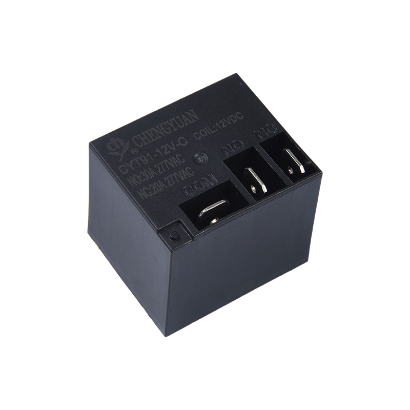
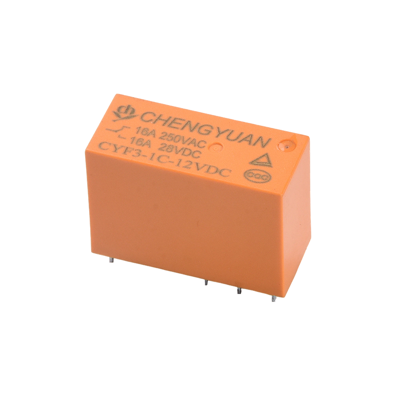
High-Current Compact Design: Achieves high load switching capacity of 20A/30A in a small volume, offering high power density and saving installation space.
Reinforced Current-Carrying Structure: Optional copper terminal version provides lower contact resistance and stronger current-carrying capacity, reducing heat generation and improving long-term reliability under high current.
Wide Voltage Drive: Wide coil operating voltage range (3-48VDC), especially suitable for automotive electronics, battery-powered equipment, and various DC control systems.
2. Key Features
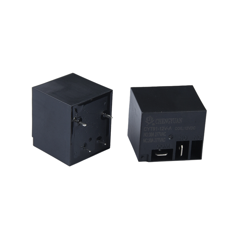
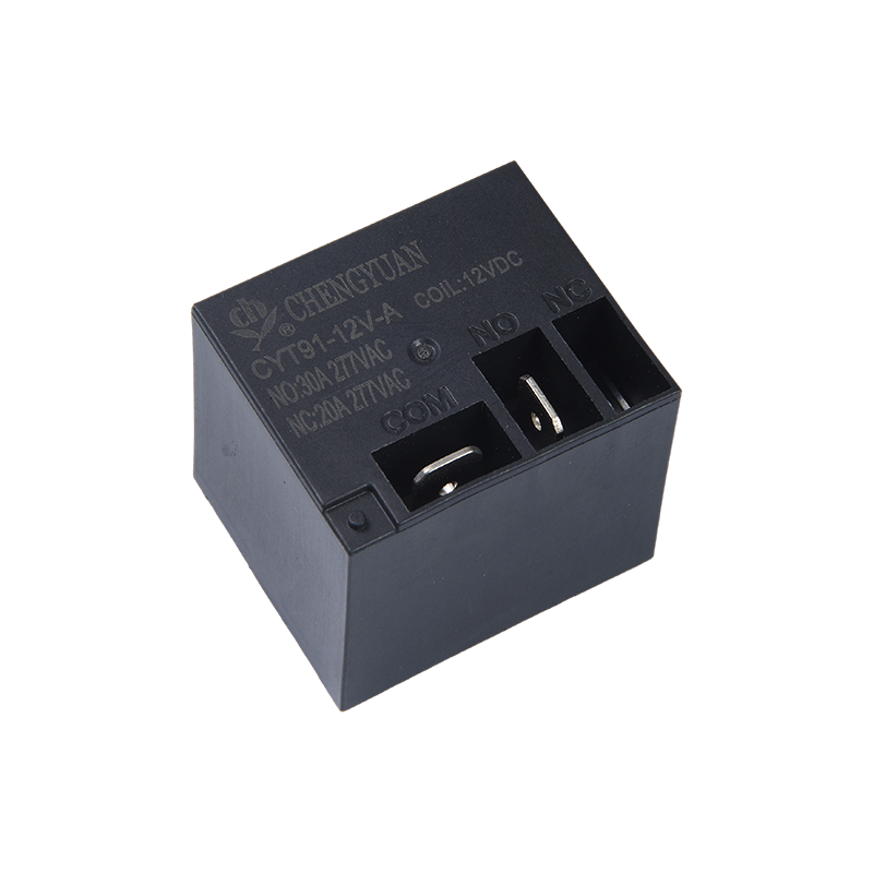
Load Capacity: Supports load switching up to 30A @ 250VAC or 28VDC, meeting the control needs of most high-power resistive and inductive loads.
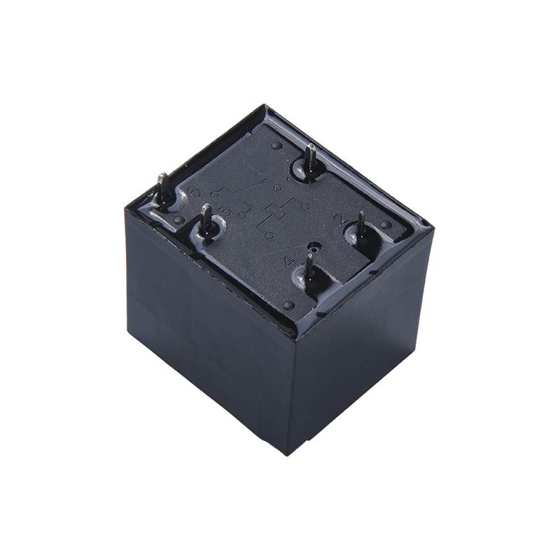
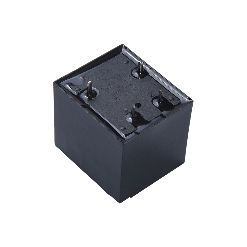
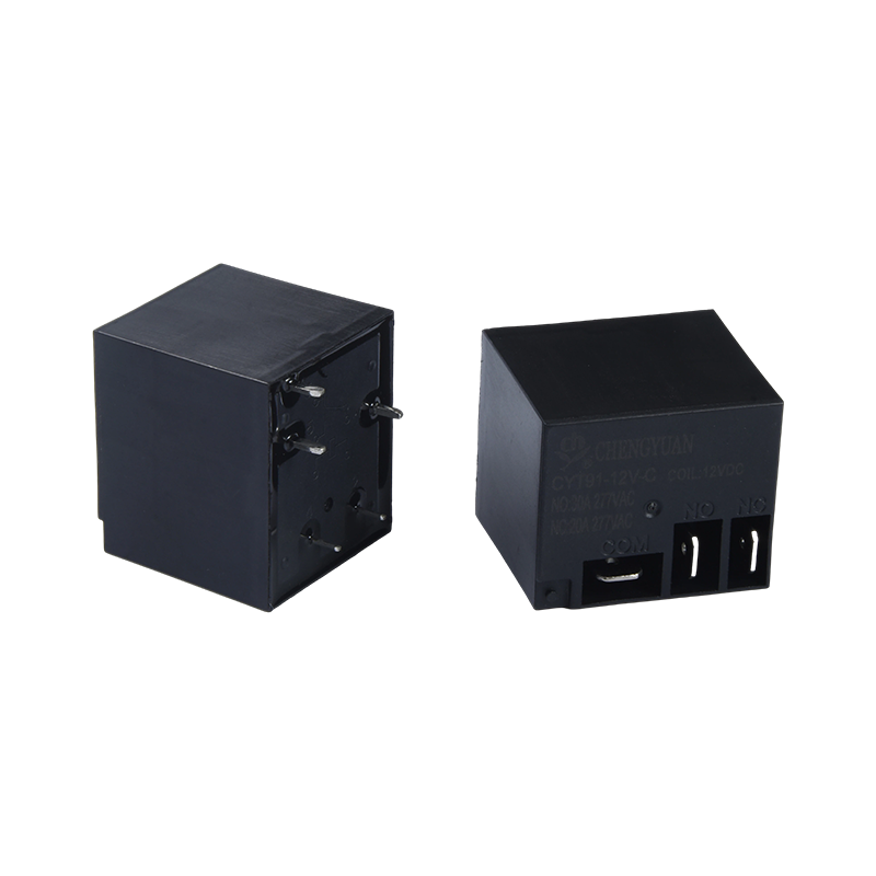
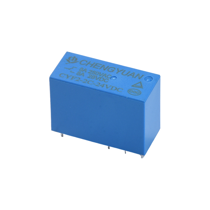
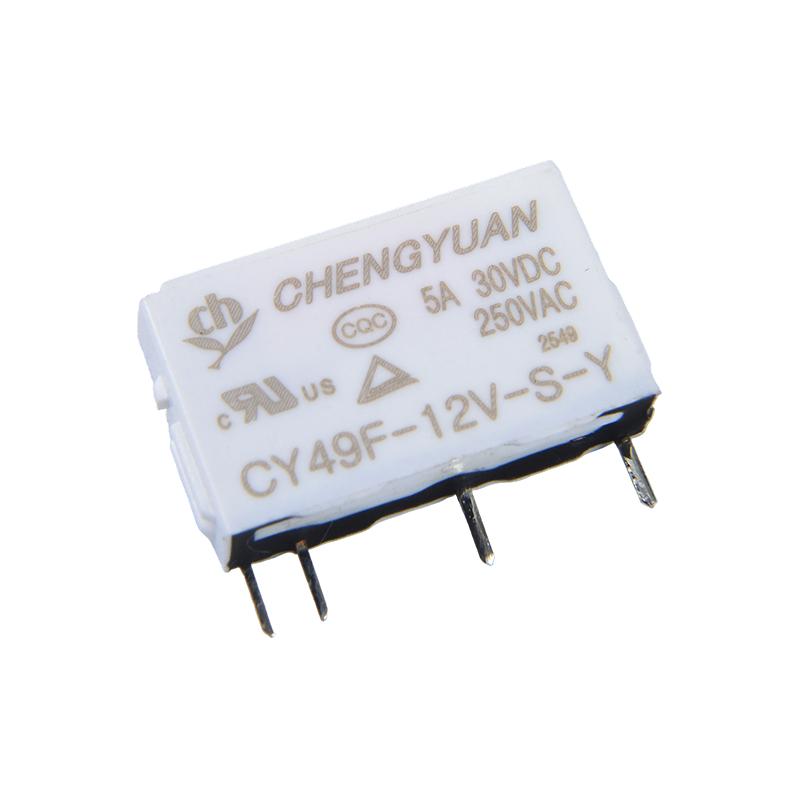
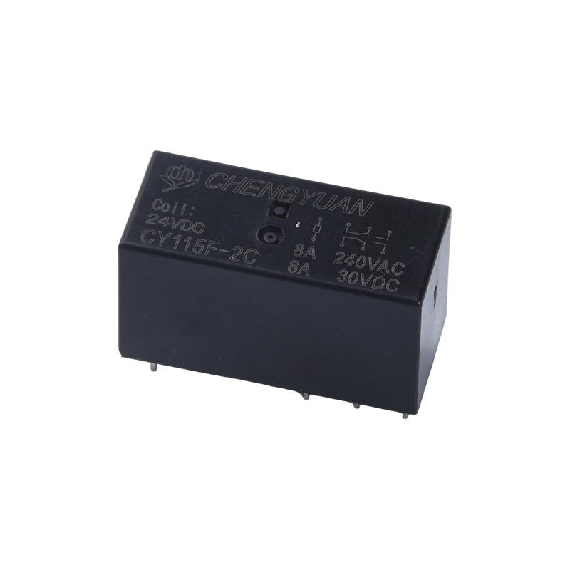
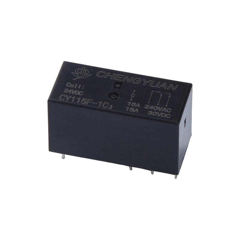
Contact Configuration: Uses an SPDT (Single Pole Double Throw) structure, providing one normally open and one normally closed contact, suitable for simple circuit switching or on/off control.
Efficient Drive: Typical coil power consumption is 0.9W, offering high driving efficiency and low burden on the control circuit.
Durable Design: Robust structure, contact materials and pressure optimized for high-current arcing, resulting in a long electrical life.
3. Main Applications
Automotive Electronics: Used in electric vehicles and traditional vehicles for battery management, pre-charge circuits, heaters, blowers, and high-power lighting control.
Industrial Equipment: Controls small and medium-sized motors, compressors, industrial heaters, and power distribution units.
Home Appliances: Used in instantaneous water heaters, high-power kitchen appliances, air conditioner compressors, and heating equipment requiring high-current switching.
Energy Control: Serves as the main control switch for high-current DC circuits in solar systems and charging equipment.
|
Contact Data
|
|
Type
|
CYT91
|
|
Contact material
|
Silver alloy
|
|
Contact resistance
|
100mΩ Max.(at 1A 6VDC)
|
|
Rated load (Resistive load)
|
20A/30A 250VAC
|
|
Max. switching current
|
20A/30A
|
|
Max. switching voltage
|
250VAC
|
|
Max. switching power
|
5000VA/7500VA
|
|
Characteristics
|
|
Operate time (at rated coil voltage)
|
15ms Max. (No diode)
|
|
Release time
|
10ms Max. ( No diode)
|
|
Insulation resistance
|
Min. 1000MΩ (at 500VDC)
|
|
Dielectric strength
|
Between open contacts:1500VAC, 50/60Hz for 1min
|
|
Between coil and contact : 2500VAC , 50/60Hz for 1min
|
|
Vibration resistance
|
Destructive
|
10-55Hz ,at double amplitude of 1.5 mm
|
|
Functional
|
10-55Hz ,at double amplitude of 1.5 mm
|
|
hock resistance
|
Functional
|
10G Min.
|
|
Destructive
|
100G Min.
|
|
Endurance
|
Mechanical endurance (10800ops./h)
|
10000000 ops.(at room temperature)
|
|
Electrical endurance (360ops./h)
|
100000 ops.(at room temperature)
|
|
Ambient atemperature
|
-40℃~+85℃( no condensation)
|
|
Weight
|
Approx.28g
|
Coil Data (at 20℃)
|
Nominal
voltage
(VDC)
|
Nominal
operating
current
±10%(mA)
|
Coil resistance
±10%(Ω)
|
Nominal operating
power
|
Operate voltage
(Max.)
|
Release voltage
(Min.)
|
Max. allowable voltage
|
|
5
|
180
|
27
|
Approx 0.9W
|
75% of nominal
voltage
|
5% of nominal
voltage
|
130% of nominal voltage
|
|
6
|
150
|
40
|
|
9
|
100
|
90
|
|
12
|
75
|
160
|
|
15
|
60
|
250
|
|
18
|
50
|
360
|
|
24
|
37.5
|
640
|
|
48
|
18.75
|
2560
|
The data shown above are initial values. Do not apply maximum allowable voltage on the coil for more than 10 minutes to avoid overheating of the coil.
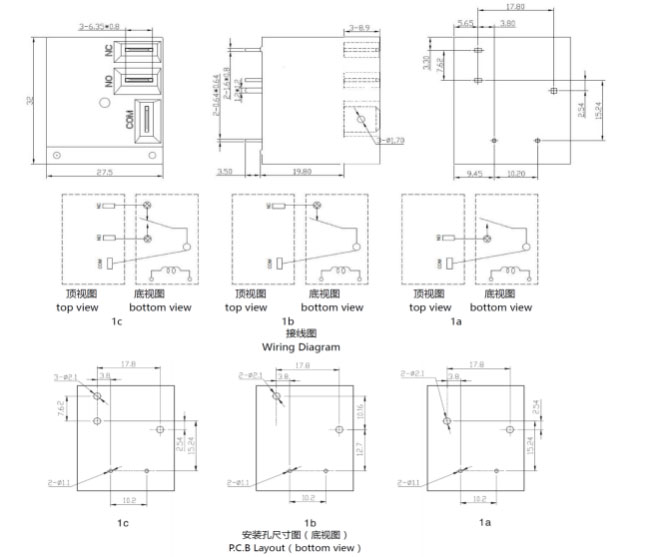
Outline dimension, Wiring diagram, PCB layout (Unit:mm)
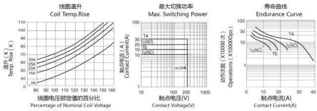
Characteristic Curves
Ordering Information
CYT91 - 1 - C - 12VDC - B - D - S - XX
1 2 3 4 5 6 7 8
1:Type:CYT91
2: Number of Poles: 1-1Pole
3: Contact Arrangement: : A Form A ; B Form B ; C Form C
4: Nominal Voltage: 5,6,9,12,15,18,24,48VDC
5: Enclosure Color: B-Black; L-Blue
6: Coil Pwor: D-0.9W
7: Protective Construction: S-Flux proofed,
SH- Sealed type washable
8: Special Parameter: Nil-Standard type
Letter or number-Special requirement
Flux-proof relays can not be used in the environment with pollutants like H2S, SO2, NO2, dust, etc.
Water cleaning or surface process is not suggested after the flux-proof relays are assembled on the PCB.
Disclaimer: The specification is for reference only. Specifications are subject to change without prior notice.
We could not evaluate all the performance and all the parameters for every possible application. Thus, the users should be in the right position to choose
Suitable product for their own application. For sealed relays, after installation and cleaning, please open the ventilation hole in the case before use. If there is any query, please contact Chengyuan for technical services. However, it is the user`s responsibility to determine which product should be used.
 English
 中文简体
中文简体 Español