Different Types of Electrical Contactors: How to Compare and Choose OneDifferent Types of Electrical Contactors: How to Compare and Choose OneDifferent Types of Electrical Contactors: How to Compare and Choose OneDifferent Types of Electrical Contactors: How to Compare and Choose OneDifferent Types of Electrical Contactors: How to Compare and Choose OneDifferent Types of Electrical Contactors: How to Compare and Choose OneDifferent Types of Electrical Contactors: How to Compare and Choose OneDifferent Types of Electrical Contactors: How to Compare and Choose OneDifferent Types of Electrical Contactors: How to Compare and Choose OneDifferent Types of Electrical Contactors: How to Compare and Choose OneDifferent Types of Electrical Contactors: How to Compare and Choose OneDifferent Types of Electrical Contactors: How to Compare and Choose OneDifferent Types of Electrical Contactors: How to Compare and Choose OneDifferent Types of Electrical Contactors: How to Compare and Choose OneDifferent Types of Electrical Contactors: How to Compare and Choose OneDifferent Types of Electrical Contactors: How to Compare and Choose One
News
Home / News / Industry News / Different Types of Electrical Contactors: How to Compare and Choose One
Different Types of Electrical Contactors: How to Compare and Choose One
A 25 A contactor that keeps burning out its coil is usually not a faulty contactor. It is the wrong contactor for the job. In a familiar pattern, the device sits in a hot enclosure, the control supply sags to 85 percent of nominal during every motor start, and the coil is held in for hours at a time. The contactor is doing exactly what it was told to do, but the family it belongs to was never designed for that duty.
Seven families of electrical contactors turn up in real panels: standard AC electromagnetic, DC electromagnetic, definite purpose, reversing, magnetic latching, vacuum, and solid state. The choice between them comes down to four questions. How much current must be switched? How often? What does the load look like at the instant the contacts open? And what should the coil do when control power is lost or restored? Answer those four and the family selects itself.
The sections below cover what each family does well, where it fails, and the numbers that separate one from another. Ratings and life figures are planning values, so confirm them against the datasheet of the exact part before ordering.
What a Contactor Has to Do Before Anything Else
A contactor is a remotely operated switch built for repeated duty. It has to close against inrush current without welding its contacts, carry the running current without overheating, break an arc without burning itself up, and do all of that tens of thousands of times. Every type of contactor is a different set of compromises against those four demands.
The hardware is similar across families:
Coil or electromagnet, which turns control voltage into mechanical force
Fixed contacts and moving contacts, sized for the load current
A contact spring that sets contact pressure, plus a return spring that opens the gap
An arc chute or a magnetic blowout that stretches and cools the arc
A frame or enclosure that holds the gap and insulates the poles
Auxiliary contacts that report state back to the control circuit
Contact pressure is the quiet variable. A spring that is too light allows bounce and micro arcing, while one that is too heavy forces the coil to work harder and wears the mechanism faster. That trade off is why a contactor rated 40 A for resistive heating may only be rated 25 A for a motor load.
The Main Types of Electrical Contactors
These are the families you will meet in industrial and commercial panels, roughly in the order they appear in the field.
Standard AC Electromagnetic Contactors
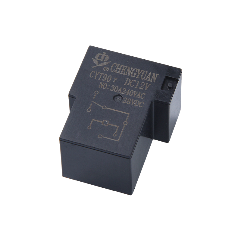
This is the workhorse. A laminated AC coil pulls an armature, closes three or four poles, and holds them with continuous coil current. IEC style frames run from about 9 A to 95 A in the common sizes, and coils usually cover 24 V to 400 V at 50 or 60 Hz. The weak point is the coil itself: a shading ring keeps it from chattering, but the ring and the coil insulation are the parts that suffer most when control voltage sags or the ambient gets hot. Below the motor starter sizes, a heavy duty electromagnetic relay in a compact frame often does the same job at 30 A to 40 A and saves panel space.
DC arcs behave differently because there is no zero crossing to extinguish them. A DC contactor therefore adds a blowout magnet or a longer arc chute, and often uses an economiser circuit or a permanent magnet to cut holding current. Industrial sizes run from a few amperes up to about 40 A, with battery, solar, and DC drive circuits as the main applications. Coil polarity matters on many DC contactors, and reversing the control wires can leave the device permanently closed or permanently open.
Definite Purpose Contactors
These are built for one narrow application, most often HVAC compressors, fans, and pumps. They typically switch 20 A to 40 A, cost less than a general purpose IEC frame, and carry a fixed coil and a fixed terminal layout. The trade off is flexibility: accessory blocks, interchangeable coils, and spare contact kits are usually not available, so a change in control voltage means a new contactor rather than a new coil.
Reversing Contactors
A reversing contactor is two contactors joined by a mechanical interlock, with an electrical interlock in the control circuit. One unit handles forward rotation and the other handles reverse, and the two coils must never be energised together. The critical detail is dead time: a simultaneous close creates a phase to phase fault across the mains. Mechanical interlocks are the primary protection and electrical interlocks are the backup. Hoists, conveyors, and door drives are the classic applications.
Magnetic Latching Contactors
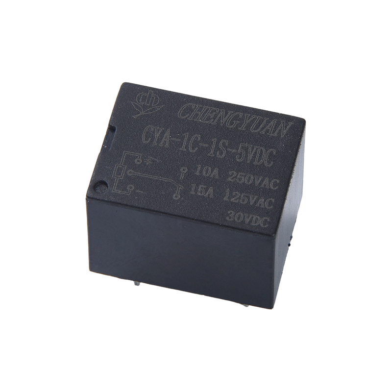
A latching contactor uses a short pulse to change state and a permanent magnet to hold it. Holding power drops to zero, which matters in energy metering, remote switching, and battery powered panels. The consequence is that the device remembers its last command after a power failure, so a feedback contact is essential whenever the controller needs to know the real position. Understanding how a magnetic latching relay keeps its state is useful here, because the same mechanical principle appears in latching contactors.
In a vacuum contactor the contacts sit inside a sealed ceramic bottle. With no air to ionise, the arc is extinguished almost immediately and the contact gap can be very short. These units handle 100 A to 400 A and above at medium voltage, which makes them common in mining, heavy motor drives, and utility switching. Cost, size, and the need to replace complete vacuum bottles rather than individual contacts are the main drawbacks.
Solid State Contactors
A solid state contactor has no moving parts at all. Thyristors or triacs do the switching, so the device can cycle thousands of times per hour without wear, which fits heating elements, lighting, and fast process control. Two cautions follow. First, the semiconductor drops voltage and produces heat, so a heat sink or forced air is required. Second, there is no physical air gap when the device is off, so a small leakage current flows and a separate disconnect is needed for safe isolation.
Current Ratings Across the Main Families
Current rating is the first filter, because it decides frame size, terminal size, and how much copper has to bend inside the panel.
Typical upper continuous current rating by contactor family, in amperes
Vacuum
400 A
Solid state
100 A
Standard AC frame
95 A
Magnetic latching
63 A
Definite purpose
40 A
Reversing
32 A
Miniature frame
16 A
Illustrative planning values, not measured test data.
The chart shows the upper end of the common industrial range for each family, not a hard limit that a device can never exceed. Vacuum contactors reach 400 A and beyond, which places them in a different class of panel with different cable and busbar practice. Solid state and standard AC electromagnetic contactors overlap closely between 95 A and 100 A, so the decision between them is usually about cycle rate and heat rather than current. Magnetic latching and definite purpose units fill the middle band from 40 A to 63 A, where coil power and panel space matter more than raw rating. Reversing and miniature frames stay below 32 A, because the added mechanism or the small contact gap limits what the contacts can carry. Use this as a first pass to narrow the list, then check the device rating for the exact load category, since the same frame can carry two very different numbers on its label.
Comparing Switching Technologies Side by Side
Scoring each technology against the criteria that decide most specifications is a quick way to see where the trade offs sit, and the scale below runs from one to five, where five is the most favourable.
Radar comparison of AC electromagnetic, solid state and magnetic latching contactors
AC electromagneticSolid stateMagnetic latching
Illustrative scoring on a one to five scale, not measured test data.
A standard AC electromagnetic contactor scores well on inrush withstand and cost, and less well on switching speed and holding energy, because its coil draws current for as long as the device is closed. A solid state contactor reverses that shape: it switches almost instantly and wastes very little control energy, but it offers no physical contact gap and a much higher purchase price. A magnetic latching contactor sits in the middle on most axes and stands out on holding energy, since it consumes nothing once it has changed state. The shape of each polygon is more useful than any single score, because it shows which weakness you are accepting. If two families score equally for your application, the deciding factors are usually panel space, the control voltage available, and how many operations per hour the device has to survive.
What Load Type Does to Contact Life
Contact life is always quoted for a load category, and the gap between categories is wider than most buyers expect when they read a quotation.
Expected contact life in thousands of operations against load current
Resistive loadMotor load
Illustrative planning values, not measured test data.
The upper curve shows a resistive or lightly inductive load, where the current crosses zero twice per cycle and the arc dies quickly. The lower curve shows a motor load, where the inrush current is five to eight times the running current and the arc lasts longer at every break. At 5 A the two curves start close together, but by 40 A the resistive curve is roughly four times higher than the motor curve. That gap is why one contactor frame can carry two very different numbers on its label, and why a 40 A device sold for heating duty may only be approved for about 25 A of motor duty. When you compare quotations, compare the utilisation category as well as the current, because a unit specified for resistive loads will not survive a motor starter for long.
What Fails in the Field
Field returns are a useful cross check, because the failure mix says more about installation and load data than about the contactor family itself.
Share of reported contactor failures by root cause
34
22
18
14
12
Coil failure
Contact welding
Mechanical wear
Loose terminals
Dust and moisture
Illustrative field patterns expressed in percent of returns, not measured test data.
Coil failure dominates the list, and in most cases the coil is the messenger rather than the cause: sustained undervoltage, high ambient temperature, or a mechanical jam all end in a burnt coil. Welded or heavily pitted contacts come next, and they usually point to an inrush current that is larger than the contact rating allows, or to too many operations per hour. Mechanical wear of the armature and the linkage is the slow and predictable failure that shows up after years of service. Loose or oxidised terminals and contamination from dust and moisture are installation and enclosure problems, and between them they account for roughly a quarter of returns. All five causes are cheaper to prevent at the specification stage than to repair in the field, which is why accurate load data and a realistic ambient figure are worth the extra hour of work.
A Selection Table and Checklist
The table below is a starting point for general industrial panels. It is not a substitute for the datasheet, but it narrows the list quickly.
Table 1. Planning figures for the main contactor families in general industrial panels. Confirm every value against the datasheet of the exact part.
Family
Typical switching current
Coil behaviour when closed
Best fit
Watch out for
AC electromagnetic
9 A to 95 A
Continuous coil current, several watts
Motor starters and general switching
Coil hum and drop out at low control voltage
DC electromagnetic
1 A to 40 A
Continuous, often with an economiser
Battery, solar and DC drive circuits
Arc blowout and coil polarity
Definite purpose
20 A to 40 A
Continuous
HVAC compressors, fans and pumps
Fixed coil and few accessories
Reversing
9 A to 32 A
Continuous, one coil per direction
Hoists, conveyors and door drives
Interlock failure creates a phase fault
Magnetic latching
16 A to 63 A
None, the state is held by a magnet
Energy metering and remote switching
State feedback is essential
Vacuum
100 A to 400 A
Continuous
Heavy motors and medium voltage
Complete bottle replacement
Solid state
10 A to 100 A
Low, but heat sinking is required
Fast cycling, heating and lighting
Leakage current and no air gap
Work through the following list before you ask for a quotation:
Confirm the load current and the utilisation category, not just the motor nameplate amps.
Measure or estimate the ambient inside the enclosure with the door closed.
Note the control voltage available and how far it may sag during a start.
Count the expected operations per hour and per year.
Decide what the device must do after a power failure: open, stay closed, or hold its last state.
Check whether the panel needs a physical air gap for safe isolation.
Confirm terminal size, mounting rail, and accessory blocks before ordering.
Contactor or Relay, Where the Line Sits
The line between a contactor and a relay is not a single number. It is a combination of current, duty, and design intent. Relays usually switch lower currents and are built for control logic and signal paths, while contactors are built for load switching with an arc chute and a heavier mechanism. The overlap is real, though: a high current electromagnetic relay can switch 30 A to 40 A, which covers small pumps, heaters, and lighting circuits where a full contactor frame would be oversized.
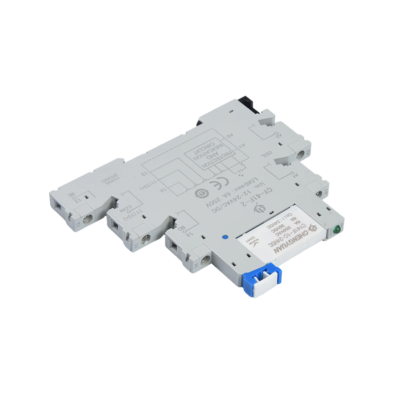
In those cases a rail mount module keeps replacement simple and the wiring tidy, because the device can be swapped without disturbing the panel wiring.
Every specification above depends on the device being built to it. Ningbo Chengyuan Chuangke Electronics has been manufacturing relays and control components in Ningbo since 1996, and its catalogue covers general purpose electromagnetic relays, reed relays, magnetic latching relays, and rail mount industrial control modules. That range lines up closely with the contactor families discussed here, which helps when a panel needs a matched set of switching devices from one source rather than from three suppliers. You can read more about the manufacturer and the production and quality routine behind these parts, or send the load data and the ambient figure and let the team confirm the right frame size and coil voltage.
Pick the family first, then the frame size, then the coil voltage. A definite purpose contactor for an air conditioner, a magnetic latching unit for a remote meter, and a solid state device for a fast cycling heater are all correct answers, and each of them would be a mistake in one of the other two positions.
The four questions from the start of this guide are worth keeping on a note by the workbench: current, cycle rate, load type at the break, and coil behaviour after a power failure. When a quotation arrives without a utilisation category or an ambient rating, that is the moment to ask, because those two numbers decide whether the contactor in the box is still working in five years.
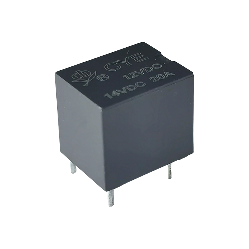
The CYE Relay is an electromagnetic relay specifically designed for automotive applications, with a nominal load of 20A 14VDC and contact switching capability up to 35 amps. This product achieves high...
The CYA-S Relay (also known as Magnetic Latching Relay, 3F Latching Relay, Single and Double Coil Magnetic Latching) belongs to the CYA-S and CYF-S (3F/14F) series of magnetic latching relays. Compare...

 English
 中文简体
 Español