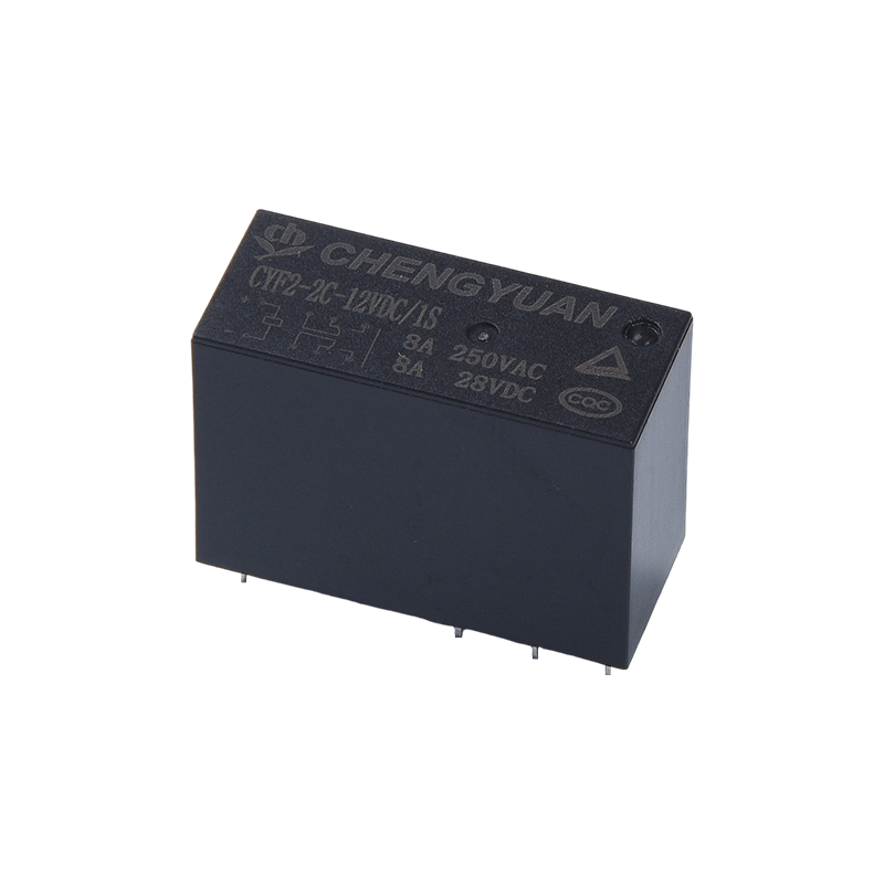
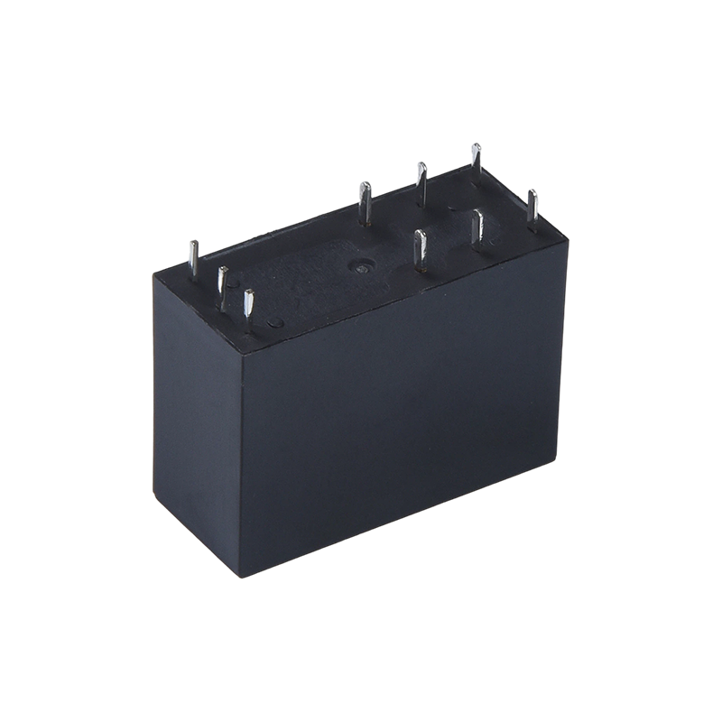
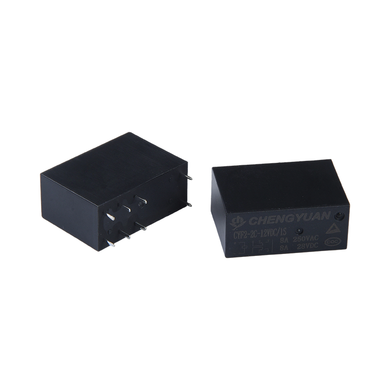
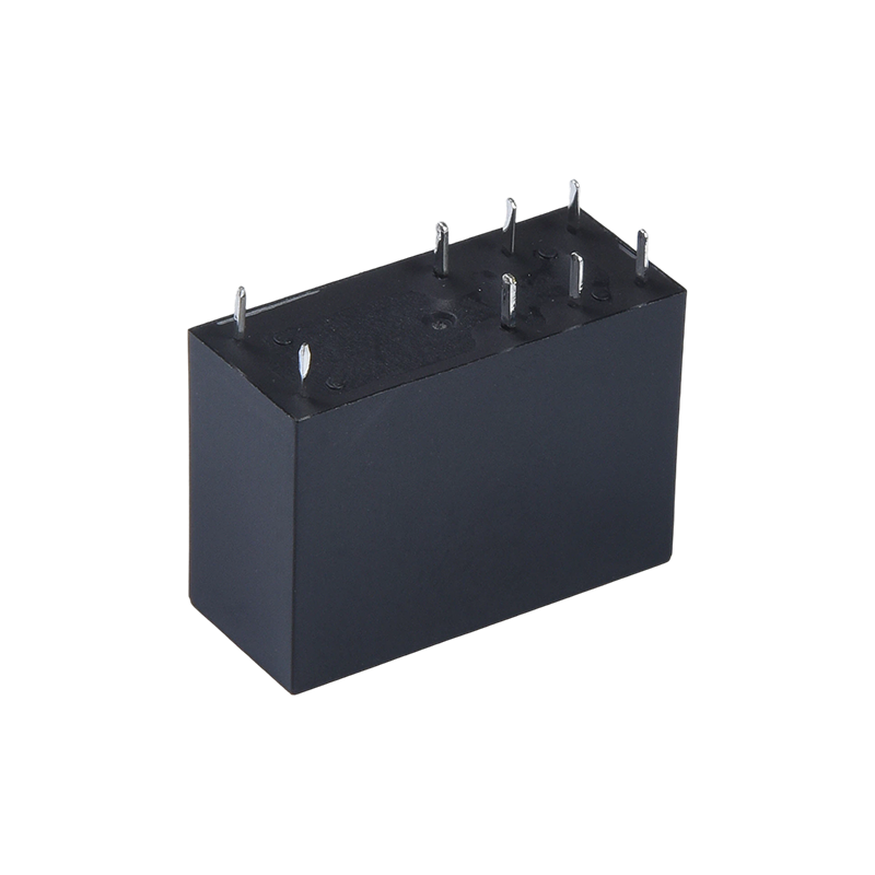
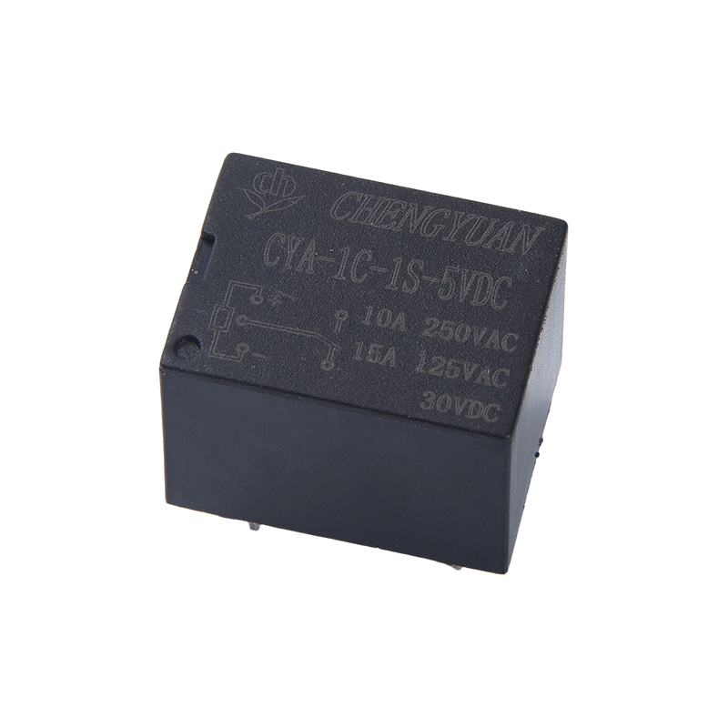
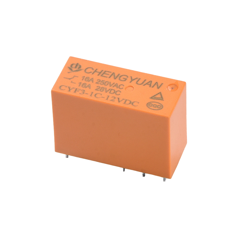
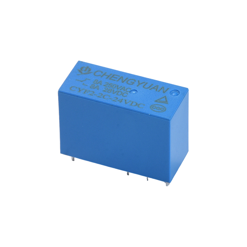
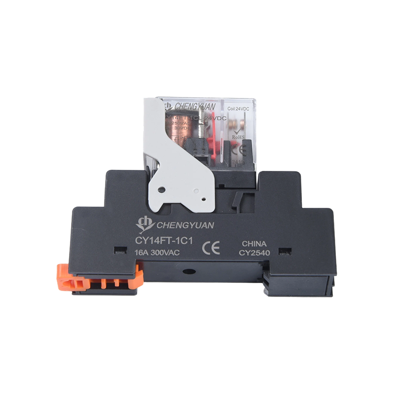
Features:
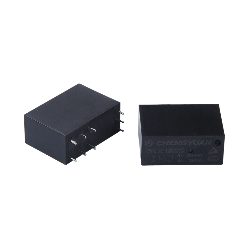
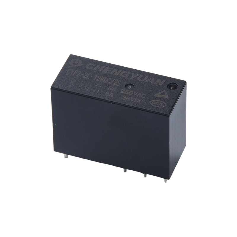
1. Magnetic Latching Function: Uses pulse excitation; the coil consumes power only during the switching moment, and the contact state is self-locked after power off, significantly reducing system energy consumption.
2. High Load Switching: Contacts support 8A current switching, meeting the high-power control needs of household appliances such as air conditioners and microwave ovens.
3. High Withstand Voltage Isolation: The withstand voltage between the coil and contacts reaches 5000V, providing excellent electrical isolation performance and ensuring the safety of the control circuit.
4. Compact Design: Small size and compact structure, ideal for high-density mounting on PCB boards.
5. Wide Voltage Coil Range: Offers various coil specifications from 3VDC to 48VDC, adapting to different control voltages.
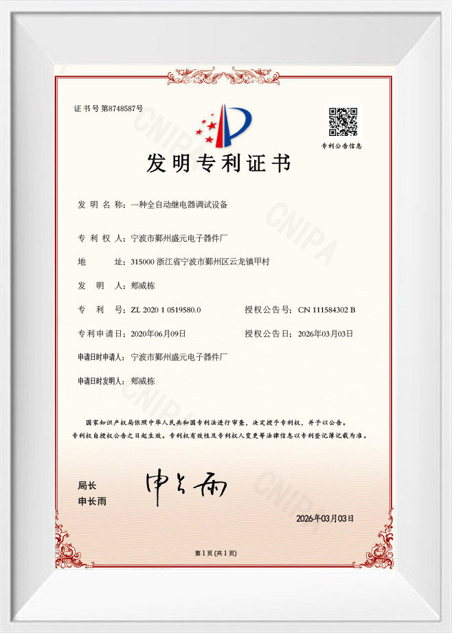
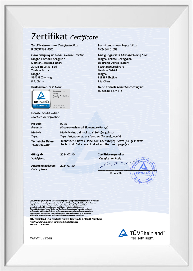
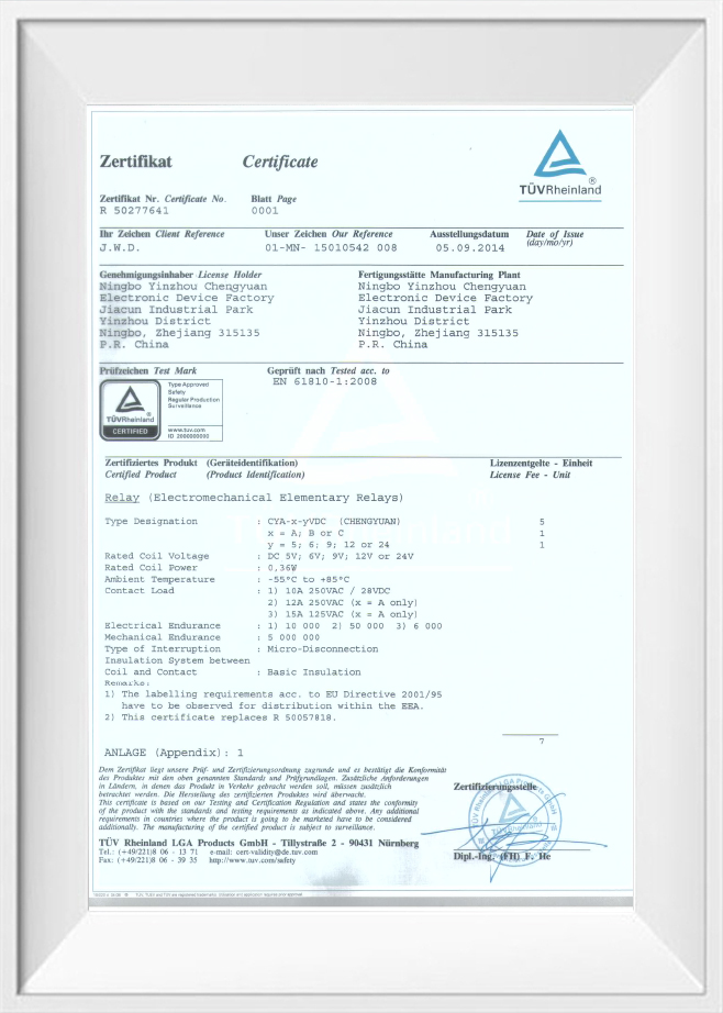
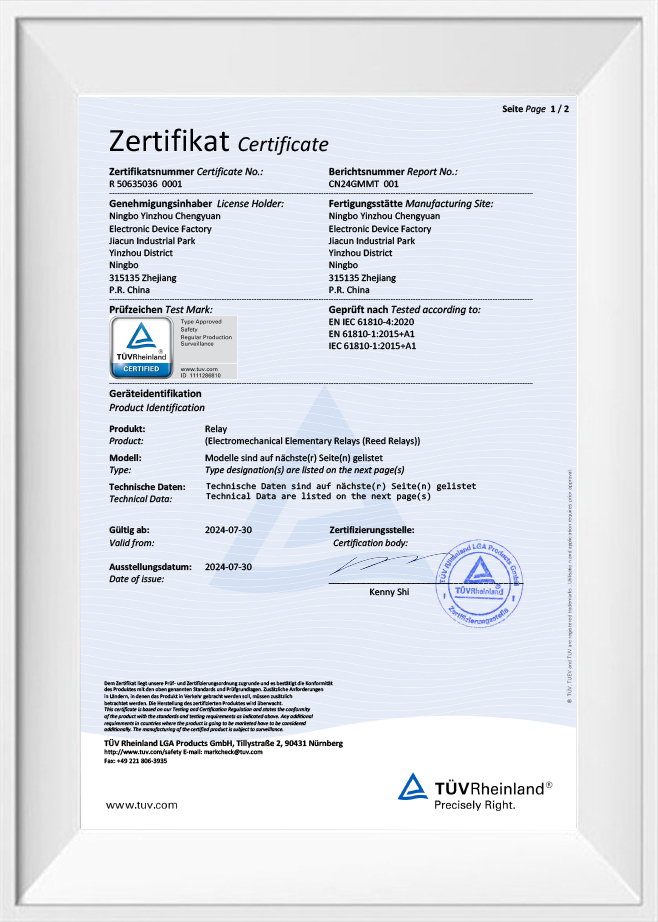
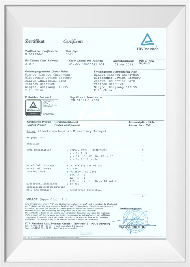
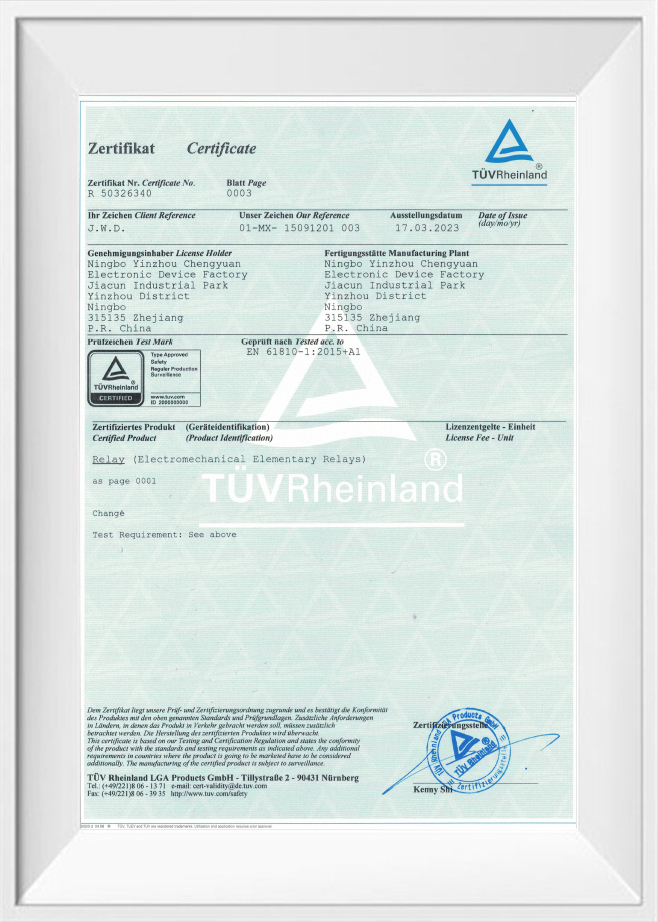
6. Safety Certification: TUV and CQC certified, complying with international safety standards.
Typical Applications:
1. Communication Equipment: Used in communication base stations and switching equipment for low-power circuit switching and signal routing.
2. Household Appliances: Suitable for air conditioners, microwave ovens, and other equipment as an energy-saving power control switch.
3. Security Equipment: Used in security alarm systems and access control to ensure that the original locking or alarm state is maintained even in the event of a power outage.
4. Office Equipment: Applied in office automation equipment, such as copiers and printers, to reduce standby power consumption.
Contact Data
|
Type
|
CYA
|
|
Contact material
|
Silver alloy
|
|
Contact resistance
|
100 mΩ max.(at 1A 16VDC)
|
|
Rated load (Resistive load)
|
10A250VAC
|
|
Max. switching current
|
15A
|
|
Max. switching voltage
|
250VAC
|
|
Max. switching power
|
2500VA
|
|
Min. switching load
|
6V 1A
|
Characteristics
|
Operating time (at rated coil voltage)
|
8ms Max. ( No diode)
|
|
Release time
|
5ms Max. ( No diode)
|
|
Insulation resistance
|
Min 1000MΩ (at 500VDC)
|
|
Dielectric strength
|
Between open contacts:750VAC, 50/60Hz for 1min
|
|
Between coil and contact: 1500VAC , 50/60Hz for 1min
|
|
Vibration resistance
|
Destructive
|
10-55Hz, at double amplitude of 1.5 mm
|
|
Functional
|
10-55Hz, at double amplitude of 1.5 mm
|
|
Shock resistance
|
Functional
|
10G Min
|
|
Destructive
|
10G Min
|
|
Endurance
|
Mechanical endurance (10800ops./h)
|
10,000,000 ops.(at room temperature)
|
|
Electrical endurance (360ops./h)
|
100,000 ops.(at room temperature)
|
|
Ambient temperature
|
-40℃~+85℃( no condensation)
|
|
Weight
|
Approx.8.5g
|
Coil Data (at 20℃)
|
Nominal
voltage
(VDC)
|
Nominal
operating
current
±10%(mA)
|
Coil resistance
±10%(Ω)
|
Nominal operating
power
|
Operate voltage
(Max.)
|
Release voltage
(Min.)
|
Max. allowable voltage
|
|
3
|
120
|
25
|
Approx 0.36W
|
75% of nominal
voltage
|
5% of nominal
voltage
|
130% of nominal voltage
|
|
5
|
71.42
|
70
|
|
6
|
60
|
100
|
|
9
|
40
|
225
|
|
12
|
30
|
400
|
|
15
|
24
|
625
|
|
18
|
20
|
900
|
|
24
|
15
|
1600
|
|
48
|
7.5
|
6400
|
The data shown above are initial values. Do not apple maximum allowable voltage on coil for more than 10 minutes to avoid overheating of thd coil.
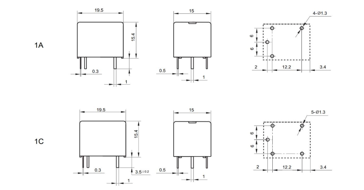
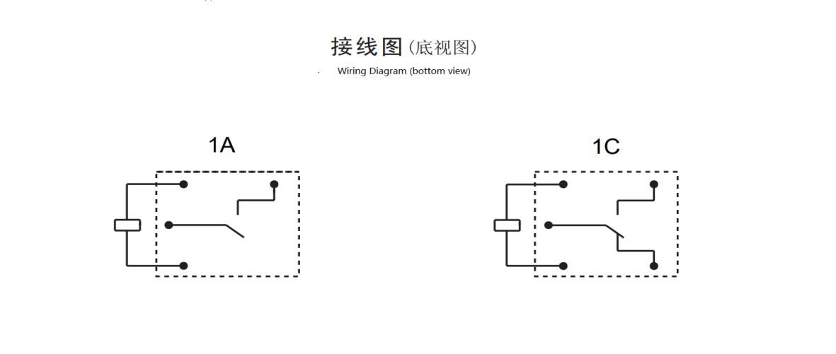
Outline dimension, Wiring diagram, PCB layout (Unit: mm)
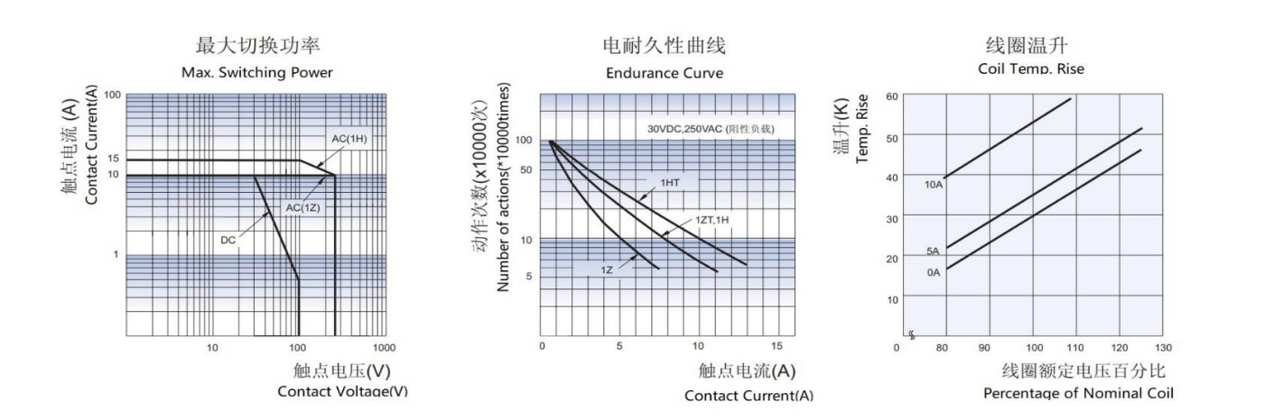
Characteristic Curves
CYA - 1 - C - 12VDC - H - D - T - XX
1 2 3 4 5 6 7 8
1: Type: CYA
2: Number of Poles: 1-1Pole
3: Contact Arrangement: C From C ; H From A ; B From B
4: Nominal Voltage: 3,5,6,9,12,18,24,48VDC
5: Enclosure Color: T -White; H-Black; L-Blue 6:Coil Power: D-0.45W L-0.36W
7: Protective Construction: S-Flux proofed,
SH- Sealed type washable
8: Special Parameter: Nil-Standard type
Letter or number-Special requirement
(1): Flux-proof relays can not be used in the environment with pollutants like H2S, SO2, NO2, dust, etc.
(2): Water cleaning or surface processing is not suggested after the flux-proof relays are assembled on the PCB.
(3): Customer-specific requirements (XX) will be evaluated by our company and then marked with characteristic symbols.

 English
 中文简体
中文简体 Español