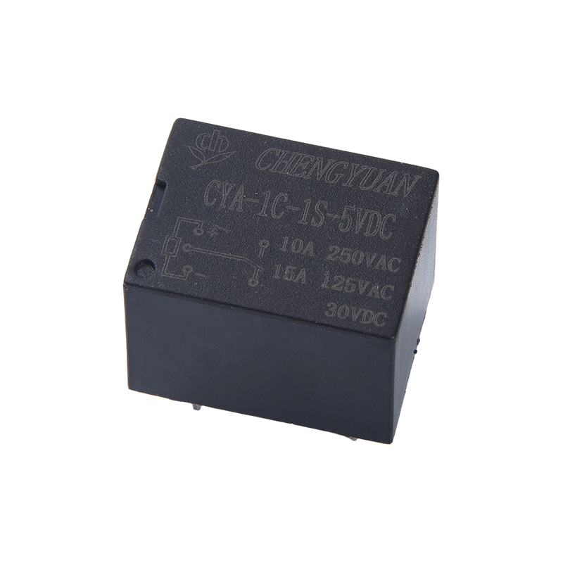
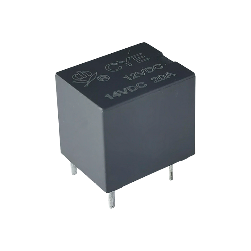
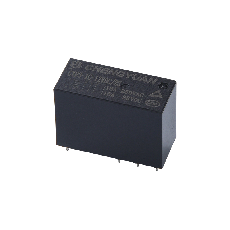
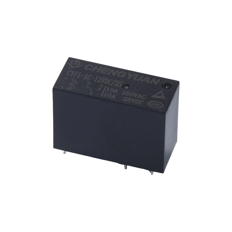
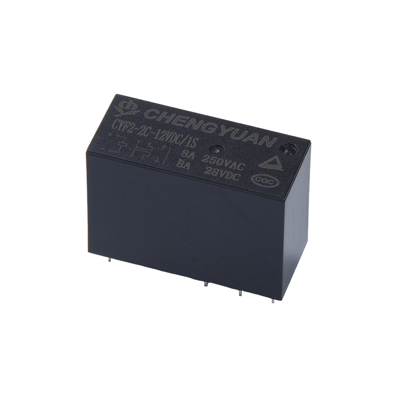
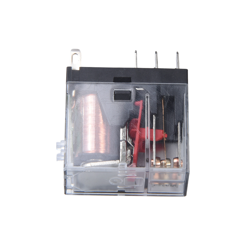
The core function of a Magnetic latching relay is to switch a circuit on or off using a short pulse of current, then hold that exact position using a permanent magnet rather than continuous coil power, so the load stays connected or disconnected even after the control signal is removed. This bistable design is what makes magnetic latching relays the standard switching component in applications where energy efficiency, remote control and long unattended operation matter more than raw switching speed. Research on smart meter relay performance testing confirms this is the relay's defining advantage, noting that a magnetic latching relay's low control energy consumption is a primary reason it is widely used in smart meters, where the relay's quality directly determines the overall reliability of the meter itself.
How the Bistable Latching Mechanism Works
A standard electromagnetic relay needs continuous coil current to hold its contacts in the energized position, which means power is constantly consumed as long as the circuit needs to stay closed. A magnetic latching relay solves this differently. According to published engineering documentation on latching relay control circuits, turning the relay on or off simply requires a momentary trigger pulse applied to the coil, where a pulse in one direction sets the relay to its first position and a pulse in the opposite direction sets it to the second position. Once that pulse ends, an internal permanent magnet holds the armature and contacts in place indefinitely, with no ongoing current draw required to maintain either state.
Basic Function Sequence
- A short trigger pulse is applied to the coil in a chosen direction
- The resulting magnetic field moves the armature to switch the contacts
- A permanent magnet locks the armature and contacts in that position
- The contacts remain in position with zero holding power until a reverse pulse is applied
- A reverse pulse resets the armature to the opposite state
Why Energy Free State Retention Is the Key Benefit
The practical value of this design shows up most clearly in energy savings. Industry data on dual pole latching relays used in metering applications shows that because magnetic latching relays consume energy only during the moment of switching and draw no power at any other time, they can save over 90 percent of the energy that a traditional continuously held relay would consume, directly reducing a device's overall operating power draw. The same latching design also reduces mechanical wear compared with relays that hold contacts under constant magnetic force, which extends product life and lowers the frequency and cost of maintenance or replacement over the device's service life.
Primary Application: Remote Disconnect in Smart Meters
The single most common use of a magnetic latching relay today is inside smart electricity meters, where it functions as the switch that connects or disconnects a customer's power supply on remote command. This function is formalized under the IEC 62055-31 standard, which sets particular requirements for static payment meters using latching relay based disconnect switches. Because the relay holds its position without ongoing power, a utility can remotely open or close a customer's connection for prepayment control, non payment disconnection, or planned maintenance, without adding meaningful standby power consumption to millions of meters operating continuously across a grid.
Why This Matters at Grid Scale
At the scale of a national metering rollout, even a small amount of standby power per meter adds up quickly across millions of units. A relay that only draws power for the fraction of a second needed to switch state, rather than continuously while a connection stays closed, materially reduces the aggregate energy overhead of the entire metering infrastructure, which is a major reason utilities specify magnetic latching relays over standard continuously held relays for this role.
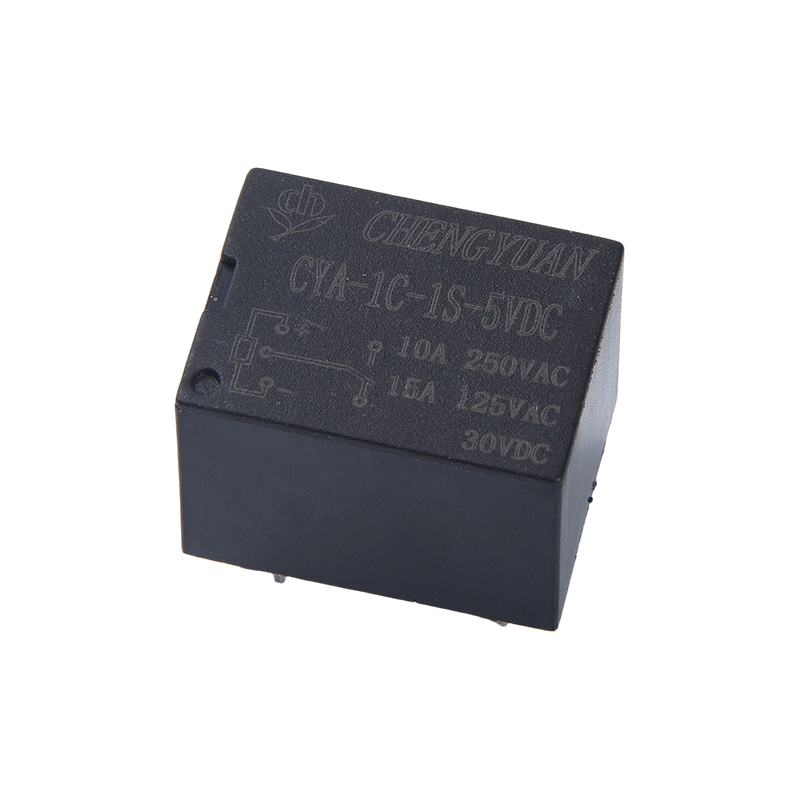
Broader Applications Beyond Metering
While smart meters remain the most demanding and widely documented use case, the same low power bistable function makes magnetic latching relays useful across a range of connected and automated systems. Application analysis published on smart home relay usage highlights several common roles:
- Lighting control, where the relay switches circuits on or off automatically based on schedules or sensor triggers
- HVAC control, managing heating, ventilation and air conditioning equipment without continuous holding power
- Home security, including controlling door or gate locks activated by a security system or mobile device
- Smoke detection systems, where the relay triggers alarms or notifications in response to a detector signal
- Renewable energy systems, helping manage the flow of energy from solar panels or wind turbines to optimize production and reduce reliance on grid power
- Smart appliances, such as controlling the operation cycle of a dishwasher or similar device to reduce energy and water usage
Built In Safety Function: Short Circuit Withstand
Because a magnetic latching relay often controls a household or building's main power connection, its safety performance under fault conditions is a critical part of its function, not an optional feature. Patent documentation on short circuit resistant latching relay design explains that global power grid reforms have driven meter companies to introduce standards specifically addressing the relay's ability to withstand and safely conduct short circuit current, following incidents of meter explosions and fires caused by uncontrolled fault currents. This has led manufacturers to define multiple operating conditions the relay must handle against short circuit events, ensuring the switching function does not become a fire or safety hazard during an electrical fault.
Key Specifications That Define Relay Function
| Specification |
What It Controls |
Why It Matters |
| Coil Voltage |
Pulse voltage needed to trigger switching |
Must match the driver circuit, commonly 6V to 48V DC |
| Contact Configuration |
Single pole or dual coil arrangement |
Determines whether one or two circuits can be independently controlled |
| Max Switching Voltage and Power |
Load the relay can safely switch |
Confirms suitability for the connected circuit, commonly up to 277VAC in metering applications |
| Dielectric Strength |
Isolation between coil and contacts |
Protects the control circuit side from load side voltage, commonly rated at 4kV |
Drive Circuit Considerations
Because a magnetic latching relay is pulse driven rather than continuously held, its drive circuit needs to generate a controlled directional pulse rather than a simple steady voltage. Published engineering guidance on this topic notes that drive circuits for latching relays are generally more complex than for standard relays, typically requiring a half bridge circuit when dual supply voltages are available, or a full bridge circuit when only a single supply voltage is present. While discrete drive circuits can be built for this purpose, dedicated driver integrated circuits are increasingly used to simplify design and ensure reliable pulse timing, which directly affects how consistently the relay switches state.
Selecting a Magnetic Latching Relay
- Confirm coil voltage and pulse duration requirements match your driver circuit design
- Choose single pole or dual coil configuration based on how many circuits need independent control
- Verify maximum switching voltage and power against your actual load, not just nominal ratings
- Check short circuit withstand ratings for any application controlling a main power connection
- Confirm compliance with relevant standards, such as IEC 62055-31 for metering applications
The function of a magnetic latching relay is to switch and then hold a circuit's on or off state using a brief control pulse and a permanent magnet, eliminating the continuous holding power that standard relays require and cutting control energy consumption by over 90 percent in typical metering applications. This makes it the practical choice for any system that needs remote, reliable switching without an ongoing power cost, from smart electricity meters and home automation to renewable energy management. A properly specified Magnetic latching relay gives designers a dependable way to add energy efficient, remotely controllable switching to devices that must operate reliably for years with minimal maintenance.

 English
 中文简体
中文简体 Español