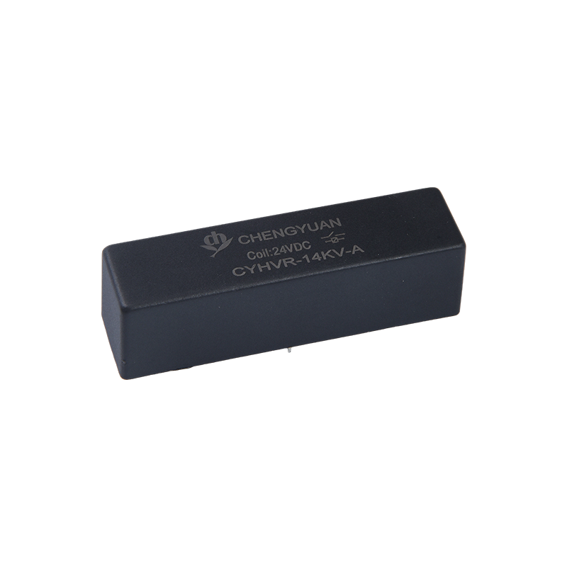
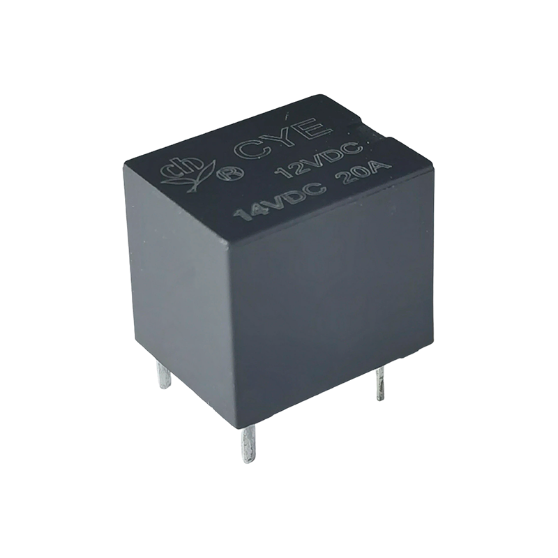
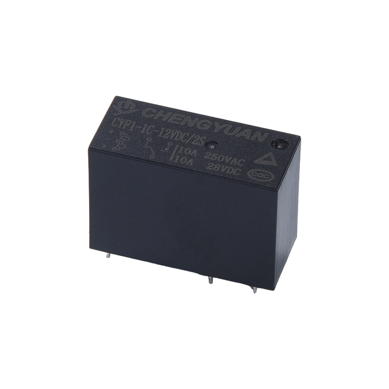
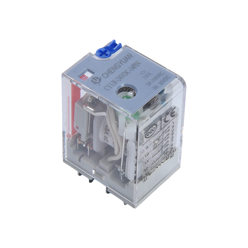
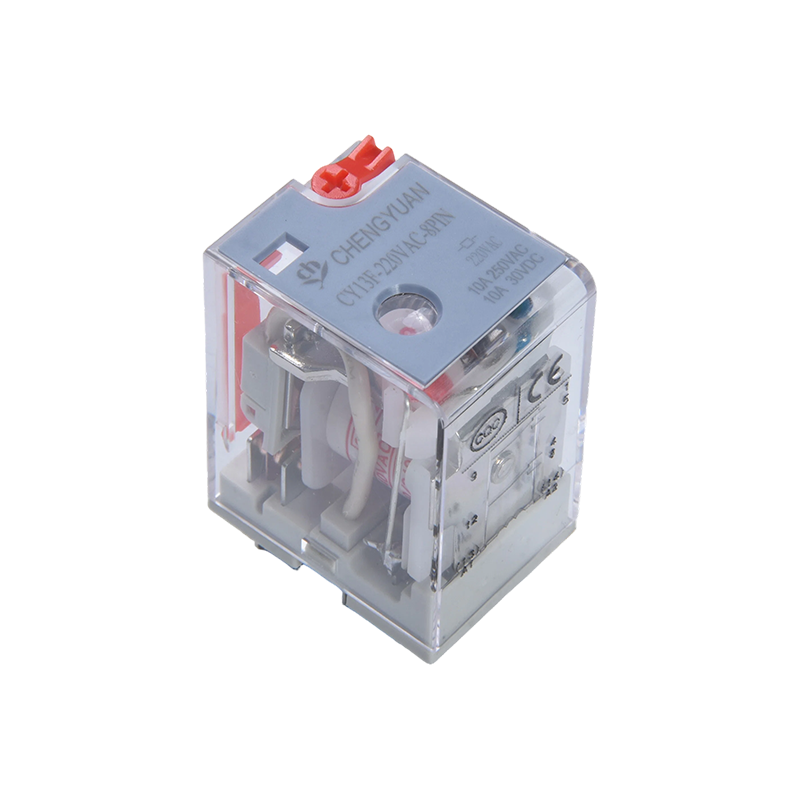
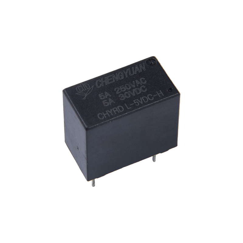
A Reed relay works by using an electromagnetic coil to create a magnetic field that pulls two thin ferromagnetic reed blades together inside a sealed glass tube, closing an electrical circuit. When current flows through the coil, the magnetic flux magnetizes the overlapping ends of the reeds with opposite polarity, causing them to attract and touch. When the coil current is removed, the natural spring tension of the reed blades pulls the contacts apart, opening the circuit. This entire cycle typically happens in less than 1 millisecond, which is why reed relays are widely used where fast, precise switching is required.
Unlike traditional electromechanical relays that rely on a separate armature and contact assembly, the reed relay combines the magnetic actuator and the switching contact into a single sealed component. This simpler mechanical structure is the core reason reed relays deliver longer life, lower contact bounce, and more consistent performance across millions of switching cycles.
The Physical Structure Behind the Switching Action
To understand the working principle fully, it helps to look at what is actually inside the device. A standard reed relay is built from three main functional parts working together.
| Component |
Function |
| Glass envelope |
Hermetically sealed tube filled with inert gas (or vacuum) to protect contacts from oxidation, dust, and humidity |
| Reed blades |
Two overlapping ferromagnetic strips, gold or rhodium plated at the contact point, that act as both the spring and the switch contact |
| Coil winding |
Copper wire wound around the glass capsule; generates the magnetic field that actuates the reeds |
| Bobbin and housing |
Holds the coil and glass capsule in a fixed position, provides insulation and terminal connections |
Because the contacts are permanently sealed inside inert gas, a Reed relay is largely immune to the contact corrosion and contamination problems that reduce the lifespan of open-frame electromechanical relays.
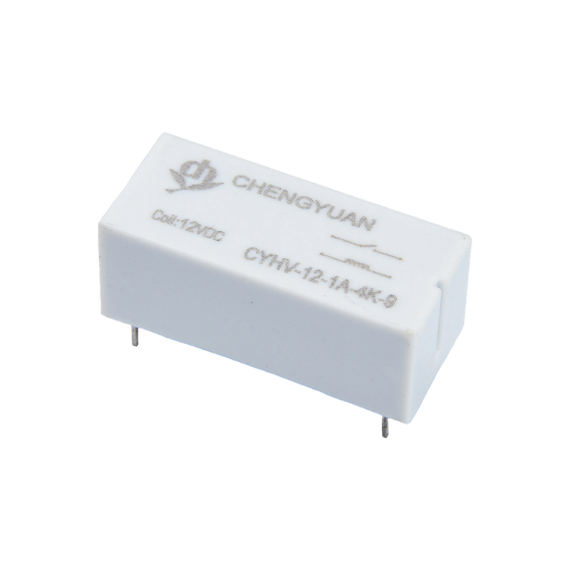
Step by Step Switching Process
The actual switching sequence can be broken down into four stages, from coil energization to contact release.
- Coil energized: Voltage is applied to the coil terminals, current begins to flow through the copper winding
- Magnetic field generated: The current produces a magnetic flux that passes through the glass tube and magnetizes the overlapping reed tips
- Contact closure: The magnetized reed tips attract each other, bending toward one another until they physically touch, completing the circuit
- Contact release: When coil current is removed, the magnetic force disappears and the spring tension built into the reed material pulls the contacts back apart
Because the reeds themselves provide both the spring return force and the electrical contact, there is no separate mechanical linkage to wear out, which explains the mechanical simplicity and durability of this design.
Common Contact Configurations
Reed relays are manufactured in a few standard contact arrangements, each suited to different circuit requirements.
| Configuration |
Also Known As |
Behavior |
| Form A |
Normally Open (NO) |
Contacts stay open until the coil is energized, then close |
| Form B |
Normally Closed (NC) |
Contacts stay closed until the coil is energized, then open |
| Form C |
Changeover (SPDT) |
Uses three reed blades so the circuit switches between two paths |
Multi-contact versions combining several Form A, Form B, or Form C switches in one package are also common in test and measurement equipment where many independent signal paths need to be controlled from a single control board.
Key Electrical and Mechanical Characteristics
According to typical reed relay datasheets and IEC 61810 relay testing standards, performance figures fall within fairly consistent ranges across the industry, which is useful for engineers comparing components.
| Parameter |
Typical Value |
| Operate time |
0.3 ms to 1 ms |
| Release time |
0.1 ms to 0.5 ms |
| Contact resistance |
Below 150 milliohms (mΩ), initial |
| Mechanical life |
Up to 1 billion operations under dry-circuit, low-load conditions |
| Switching voltage |
Up to 1000V for high-voltage variants |
| Insulation resistance |
Greater than 10^9 ohms between open contacts |
These figures come from standard IEC 61810-1 electromechanical relay test methodology combined with common industry datasheet reporting practices, and actual performance varies by coil voltage, load type, and switching frequency, so checking the specific Reed relay datasheet for an application is always recommended.
Why Reed Relays Switch Faster Than Standard Relays
The speed advantage comes directly from the working principle described above. Because the reed blades are lightweight, have very short travel distance inside the glass tube, and act as their own spring, there is far less mass to move compared with the armature and contact assembly used in a conventional electromechanical relay. Less mass combined with shorter travel distance means faster response.
Contact bounce is also reduced because the sealed inert gas environment prevents arcing byproducts from interfering with contact surfaces, and the smooth glass-to-metal seal keeps the reeds moving along a predictable path every cycle. This predictability is one reason reed relays are the preferred switching component in automated test equipment (ATE), where thousands of signal paths must be switched with microsecond-level timing accuracy.
Typical Applications
The combination of speed, sealed contacts, and small size makes reed relays suitable across several industries.
- Automated test equipment and instrumentation, for routing low-level signals between measurement channels
- Telecommunications equipment, for switching voice and data lines
- Medical devices, where sealed contacts prevent contamination and support long service intervals
- Security and access control systems, using magnetically actuated reed switches as sensors
- Industrial control panels, for isolating low-current control signals from higher power circuits
In each of these cases, the sealed, hermetic contact structure of the Reed relay reduces maintenance requirements compared with open-contact relay types operating in dusty or humid environments.
Reed Relay Compared With Other Relay Types
Choosing the right relay type depends on the switching speed, load current, and environmental conditions of the application.
| Feature |
Reed Relay |
Electromechanical Relay |
Solid-State Relay |
| Switching speed |
Very fast (sub-millisecond) |
Slower (several milliseconds) |
Fast, no mechanical delay |
| Contact life |
High, up to billions of cycles |
Moderate, limited by mechanical wear |
No mechanical wear, but limited by thermal stress |
| Contact resistance |
Very low |
Low |
Higher, due to semiconductor junction |
| Load current capacity |
Low to moderate |
Moderate to high |
Moderate to high |
| Cost |
Moderate |
Low |
Higher |
For applications involving frequent switching of low-current signals where speed and contact reliability matter most, the reed relay generally offers the best balance of performance and cost.
Selecting the Right Reed Relay for an Application
When specifying a reed relay, a few parameters deserve close attention beyond the basic working principle.
- Coil voltage and current, to match the driving circuit without exceeding power dissipation limits
- Contact rating, ensuring the maximum switching voltage and current stay within datasheet limits to avoid contact welding
- Operate and release time, particularly important for high-speed test switching applications
- Package size and mounting style, whether through-hole, surface mount, or DIP format is needed for the PCB layout
- Expected switching life, since dry-circuit low-current use extends life far beyond rated resistive load switching
Reviewing the full datasheet for a specific Reed relay model against these five parameters is the most reliable way to confirm it will perform correctly across the expected operating life of the end product.

 English
 中文简体
中文简体 Español