Contactor Wiring Guide: A1/A2 Terminals, Diagrams, and Common Mistakes to AvoidContactor Wiring Guide: A1/A2 Terminals, Diagrams, and Common Mistakes to AvoidContactor Wiring Guide: A1/A2 Terminals, Diagrams, and Common Mistakes to AvoidContactor Wiring Guide: A1/A2 Terminals, Diagrams, and Common Mistakes to AvoidContactor Wiring Guide: A1/A2 Terminals, Diagrams, and Common Mistakes to AvoidContactor Wiring Guide: A1/A2 Terminals, Diagrams, and Common Mistakes to AvoidContactor Wiring Guide: A1/A2 Terminals, Diagrams, and Common Mistakes to AvoidContactor Wiring Guide: A1/A2 Terminals, Diagrams, and Common Mistakes to AvoidContactor Wiring Guide: A1/A2 Terminals, Diagrams, and Common Mistakes to AvoidContactor Wiring Guide: A1/A2 Terminals, Diagrams, and Common Mistakes to AvoidContactor Wiring Guide: A1/A2 Terminals, Diagrams, and Common Mistakes to AvoidContactor Wiring Guide: A1/A2 Terminals, Diagrams, and Common Mistakes to AvoidContactor Wiring Guide: A1/A2 Terminals, Diagrams, and Common Mistakes to AvoidContactor Wiring Guide: A1/A2 Terminals, Diagrams, and Common Mistakes to AvoidContactor Wiring Guide: A1/A2 Terminals, Diagrams, and Common Mistakes to AvoidContactor Wiring Guide: A1/A2 Terminals, Diagrams, and Common Mistakes to Avoid
News
Home / News / Industry News / Contactor Wiring Guide: A1/A2 Terminals, Diagrams, and Common Mistakes to Avoid
Contactor Wiring Guide: A1/A2 Terminals, Diagrams, and Common Mistakes to Avoid
A maintenance electrician at a bottling line reaches for a replacement contactor after the original coil fails. The replacement sits on the bench, and the wiring diagram on the side of the old unit is torn. In most contactors, the coil terminals are labeled A1 and A2. Getting those two terminals right is the first step, but the power circuit, auxiliary contacts, and control logic need to be planned as well. This guide walks through contactor wiring from the coil terminals to the motor terminals, with the numbers and tolerances that matter in the field.
What A1 and A2 Mean on a Contactor Coil
In any contactor wiring job, the coil terminals A1 and A2 are the first pair to verify. They connect the magnetic coil to the control circuit. When voltage is applied across A1 and A2, the coil creates a magnetic field that pulls the movable contact assembly into the closed position, allowing power to flow from the line side to the load side.
On AC contactors, polarity is not critical. You can wire A1 to the phase conductor and A2 to the neutral conductor, or the reverse, and the coil will still pull in. On DC-operated contactors, polarity matters. Swapping A1 and A2 on a DC coil will not magnetize the core correctly and the contactor will hum or fail to close. Some contactors include a built-in rectifier so they can accept AC control voltage even when the coil is DC, but the coil voltage printed on the nameplate must match the control circuit voltage.
Coil voltage is a common source of wiring failure. A 230 V AC coil connected to a 24 V DC supply will not pull in. A 24 V DC coil connected to 230 V AC will burn out within seconds. Always check the nameplate before connecting the coil.
Contactor Wiring Diagram Basics
A contactor has two separate circuit paths: the power circuit and the control circuit. The power circuit carries the main current to the load. The control circuit energizes the coil and also receives feedback from the auxiliary contacts for interlocks, signaling, and status monitoring.
The power terminals on a three-pole contactor are labeled L1, L2, L3 on the input side and T1, T2, T3 on the output side. For a single-phase load, only one pole is used. The auxiliary contacts are labeled in pairs: 13/14 for a normally open contact and 21/22 for a normally closed contact. Auxiliary contacts are electrically separate from the power poles and are used for control logic, not for carrying load current.
When you wire the control circuit, the start button connects to one side of the coil through the normally open auxiliary contact. The stop button connects in series. This seals the coil after the start button is released. The normally closed auxiliary contact can be wired as an interlock to prevent the contactor from closing when another device is active. This is a standard motor starter configuration and works the same way in NEMA and IEC designs.
Contactor vs Relay: Which One Belongs in Your Circuit
Contactors and relays both use an electromagnetic coil to switch a circuit. The practical difference is current carrying capacity and mechanical endurance. A relay is designed for low-current control circuits, typically up to 10 A or less. A contactor is built to switch high-current inductive loads such as motors, heating elements, and transformers, with ratings from 9 A to hundreds of amperes.
The difference becomes obvious when you compare the physical construction. A contactor has larger contact gaps, more robust arc chutes, and a bigger coil to overcome the magnetic forces of heavy springs. A relay relies on smaller springs and a smaller coil, which makes it faster but unable to interrupt the same fault current.
The bar chart shows the typical ratings for a 9 A IEC contactor compared with a general-purpose PCB relay. The contactor handles roughly eight times the continuous current, three times the rated voltage, and ten times the expected mechanical life. The relay wins in coil power consumption and physical size, which is why relays remain the standard for control logic and signal switching. When the circuit carries over 10 A, use a contactor. When it carries control signals, use a relay. The gap in mechanical endurance is the main reason motor circuits are almost always switched by a contactor rather than a relay, since replacing a welded auxiliary contact is an expensive service call.
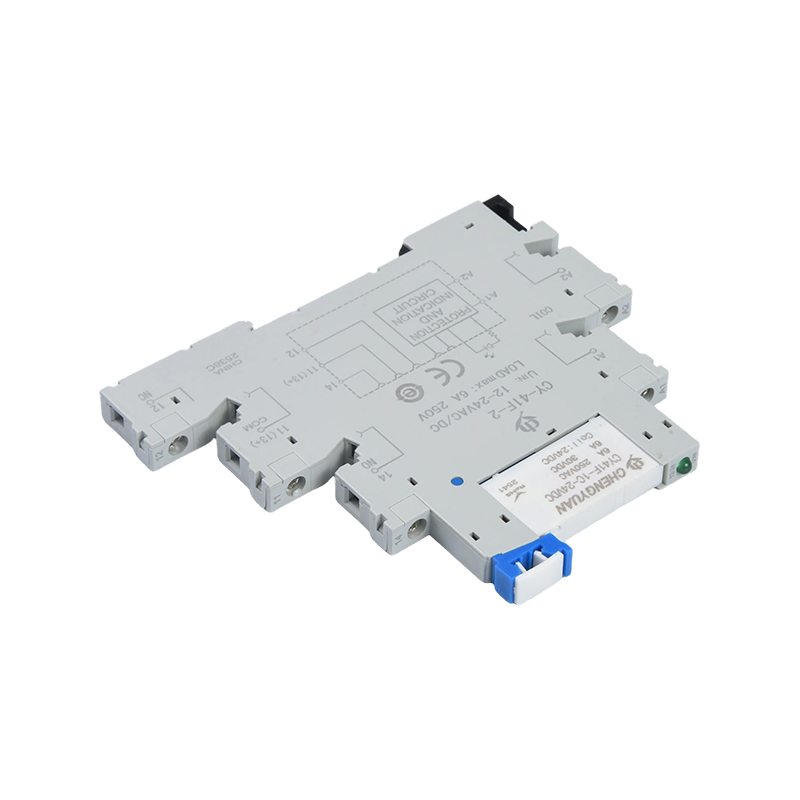
If the control logic task requires a compact DIN rail module instead of a discrete relay, a slim relay module is a practical answer. The M41F rail relay module combines the relay and its socket into one narrow package, keeping the wire count low and the panel tidy. In motor starter circuits, such modules are frequently used for the auxiliary interlock functions that do not carry the main load current.
Wiring a 3-Phase Motor Contactor Step by Step
Start by de-energizing the circuit at the disconnect switch or breaker. Verify zero voltage with a meter before touching any conductor. Then connect the three phase conductors from the supply to L1, L2 and L3. Connect the three conductors from the motor to T1, T2 and T3. Wire the coil from A1 to the neutral or common line and from A2 through the control logic to the phase line or supply.
The motor is protected by a thermal overload relay or a motor protection breaker in series with the contactor. The overload relay can be wired directly to the contactor on some designs, or installed as a separate component. Set the overload current to the nameplate full load current of the motor. A setting too low causes nuisance trips. A setting too high allows the motor to overheat.
The line chart illustrates why contactor endurance matters in real installations. With a purely resistive load, the contacts wear slowly and remain in a healthy resistance range for hundreds of thousands of operations. With an AC-3 motor load where the starting current is several times the run current, the same contactor reaches a much higher contact resistance in the same number of cycles. Arc erosion is the dominant factor under motor load because each opening of the contacts stretches a small arc that removes contact material. When contact resistance rises above 20 milliohms, heat begins to build up and the contactor should be replaced. For a motor that runs on a high-cycle schedule, selecting a contactor one frame size larger can double or triple the maintenance interval.
Choosing the Right Contactor and Control Module
Selecting the right contactor depends on the rated current, the coil voltage, the number of main poles, and whether auxiliary contacts are needed. For a 7.5 kW motor on a 400 V supply, the line current is around 15 A, so an 18 A or 25 A contactor with the same coil voltage is the typical choice. For a 22 kW motor, a 40 A contactor is required. Going one size larger than the motor current is common in industrial installations to extend maintenance intervals.
Recommended contactor frame size for common IEC motor ratings
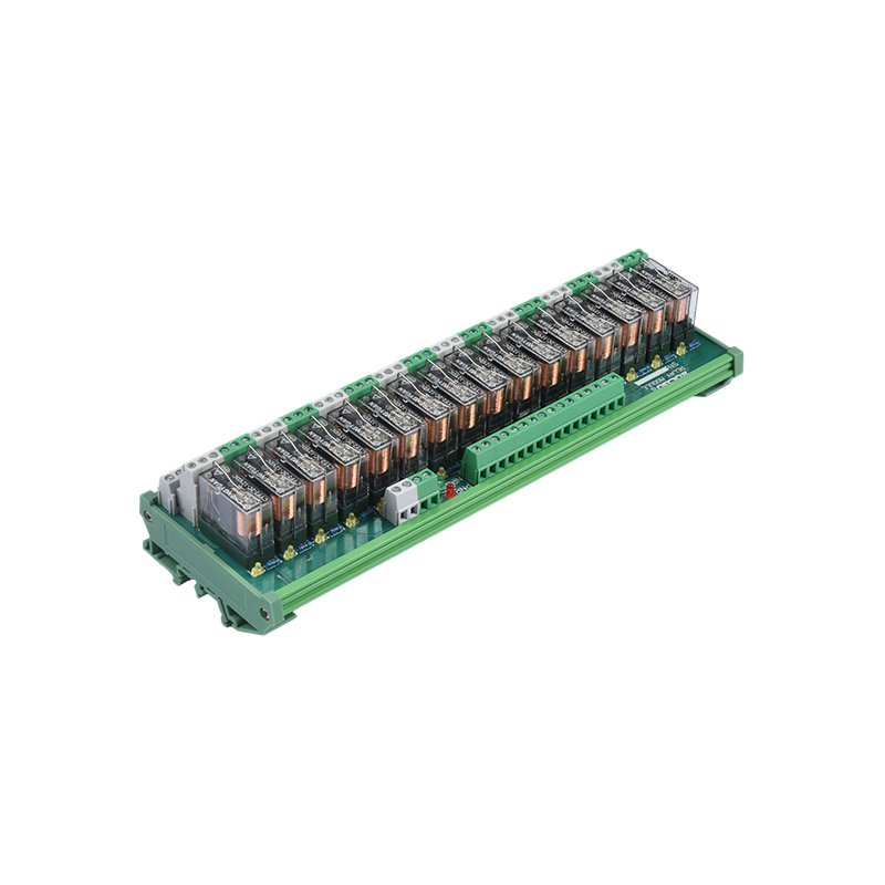
For the control logic side, an industrial module such as the MCYF1 rail relay module provides a 10 A switching capacity in a compact footprint, which is enough for most interlock circuits and pilot devices in a motor starter panel. When the control current stays below 10 A, these modules simplify the wiring by integrating the relay socket, the terminal block, and the coil status indicator into a single DIN rail device.
The radar chart compares a typical contactor with a rail relay module across five selection factors. The contactor spreads across current handling, voltage rating, and life span, reflecting its role as the main switching element in a motor circuit. The relay module shows strength in panel space efficiency, coil efficiency, and cost, because it carries only control current and fits in a narrow DIN rail slot. For an electrical engineer, the chart is a reminder that no single component covers all requirements. A hardened control panel uses both, with contactors for the main motor circuit and relay modules for the control logic. Choosing one over the other based on a single parameter, such as current rating alone, often leads to a panel that is oversized or difficult to service.
Common Wiring Mistakes and How to Avoid Them
The most frequent mistakes in contactor wiring are incorrect coil voltage, missing overload protection, and reversed auxiliary contact wiring. A coil rated for 110 V AC should not be connected to 220 V AC even for a short test, because the coil will overheat almost immediately. An overload relay set too high defeats the purpose of motor protection and leads to a burned winding.
Another common error is using the auxiliary contact to switch the main load. Auxiliary contacts are rated for low current, typically 10 A or less, and a motor inrush current will weld them shut. Always wire the power circuit through the main poles and use the auxiliary contacts only for status feedback or interlocking.
The column chart shows the coil power consumption of contactors from 9 A to 32 A. The difference between the 9 A and 32 A contactor is about three times in coil power draw. This matters for control transformer sizing in a panel shared by several contactors. A control transformer that is too small will show a voltage drop every time the contactor pulls in. A voltage drop below the coil holding voltage can cause the contactor to drop out and the motor to stop unexpectedly. When you are sizing a control transformer, add the holding power of all coils that can be energized at the same time and apply a generous safety margin.
When a control relay fails from a coil burn-out, a rail-mounted module with a 5 A or 8 A rating is a straightforward replacement. These modules accept the same control voltage ranges and can be wired in the same interlock position as a standard socket relay. For a wiring fault that may happen again, the FAQ page offers guidance on contactor failures and selection.
Testing the Contactor and Returning to Service
After wiring, test the control circuit without the load connected. Engage the start button and confirm that the contactor pulls in with a click. Release the start button and verify that the auxiliary contact seals the circuit. Then test the stop button and the overload trip. Check the tightness of all terminal screws at the nameplate torque, because loose power connections generate heat at full load.
The last check is verifying the phase sequence on a three-phase motor. Swap two phases, and the motor turns in the wrong direction, which can damage conveyor mechanisms or pump systems. Record the motor current on each phase after the motor reaches full speed. A current reading beyond the nameplate tolerance by more than 10 percent suggests an overload condition or a voltage imbalance. Use a thermal camera during the first hour of operation to spot hot connections.
If you need product guidance for a specific control circuit or an existing replacement project, contact our application engineer with the motor data and control Voltage available at the site.
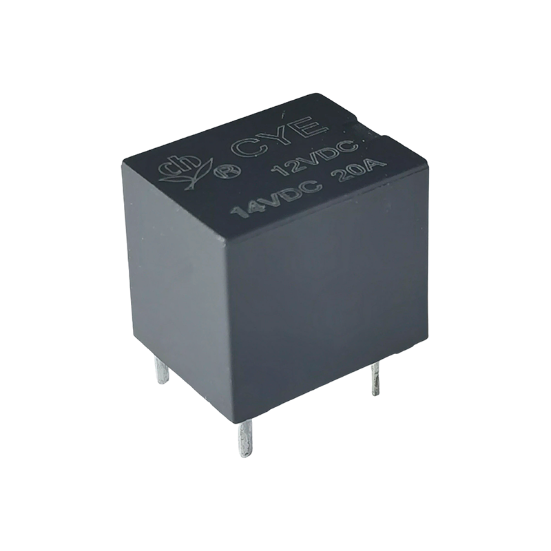
The CYE Relay is an electromagnetic relay specifically designed for automotive applications, with a nominal load of 20A 14VDC and contact switching capability up to 35 amps. This product achieves high...
Among numerous PCB-mounted relays, the CY115F1 Relay stands out with its high load capacity and broad compatibility in a compact structure. This model integrates a powerful 12A current switching capab...
The CYF1 Relay is a high-performance printed circuit board (PCB) mounted electromagnetic relay, also known as the SPSP Relay, JQX-14F Relay, or 14F power relay. This product stands out from similar pr...
The CYF2-S Relay is a magnetic latching relay with a compact 14F structure, featuring a load switching capacity of 5A to 8A and a high withstand voltage of 5000V. Unlike traditional relays that requir...
The CHYRAS Relay (also known as 4101 Relay, PCB Relay, JRC-21F, Signal Relay 4101, 0.2W 5PIN Relay) is an ultra-small signal relay. Compared to other signal relays in the same category, it features a ...
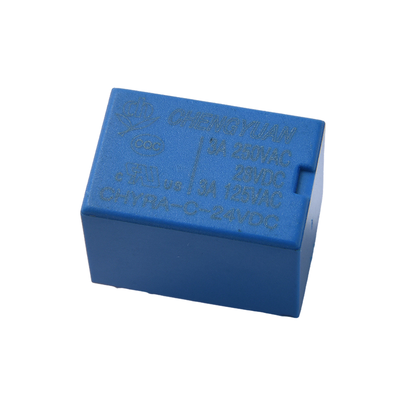
The CHYRA Relay is a miniature signal relay with a 3A-rated load capacity, featuring a special structural design that supports contact switching up to 16 amps. This product achieves isolation and cont...

 English
 中文简体
中文简体 Español