A packaging line loses its motor starter in the middle of a shift. The contactor coil has been tested and the overload relay is reset, but the PLC still shows the motor as running. The technician opens the cabinet and finds the contactor is open. No feedback is wired back to the controller, no lamp is on the door, and there is no way to know the actual state without opening the panel. The missing component is an auxiliary contact block.
An auxiliary contact block (aux contact for short) is a mechanically driven switch that follows the main contact position of a contactor or relay. It provides a separate, low-power circuit for feedback, holding, and interlock logic. This guide explains how it works, which contact arrangement fits which circuit, and where a relay module is the better choice.
What Is an Aux Contact Block?
An auxiliary contact block is a stand-alone switching assembly driven by the same mechanical motion as the main contacts. When the coil energizes, the armature moves and the block contacts open or close together with the main contacts. The auxiliary circuit is electrically separate and never carries the main load current.
Because the coupling is mechanical, the feedback reflects the real position of the main contacts. If a contactor welds closed, the aux contact shows the actual state. If the coil falls short of its pick-up voltage, the aux contact stays in the correct position. This mechanical truth is why control circuits use auxiliary contacts instead of timers or software assumptions.
Contacts inside the block use a silver alloy to keep contact resistance stable at the low voltages and currents typical of PLC inputs. A standard block is rated between 6 A and 10 A at 230 V to 690 V AC, which is higher than most control loads need but far below the main contact rating of the device it reports on.
Common contact arrangements are:
1NO: one normally open contact for positive state feedback
1NC: one normally closed contact for fault and disabled-state indication
1NO + 1NC: the general-purpose standard for most control panels
2NO + 2NC: feedback plus interlock in one block
3NO + 3NC: dense monitoring for multi-channel control systems
Blocks mount on the front or the side of a contactor, or as part of a DIN-rail relay system. Side mounting saves height; front mounting makes the wiring easier to inspect.
Why Auxiliary Contacts Are Essential in a Control Panel
Three wiring functions account for nearly every auxiliary contact in an industrial panel.
Feedback to the PLC or DCS. The controller must confirm that a motor contactor has actually closed, not merely that the coil was commanded. An aux contact creates a galvanically isolated feedback path that the controller can read as a digital input.
Holding (seal-in) circuit. In a standard start-stop circuit, an NO aux contact keeps the coil powered after the start button is released. Without it, the motor drops out the moment the operator finger leaves the button.
Interlocking. In a reversing starter, an NC contact of one contactor is wired in series with the coil of the other. This prevents the two contactors from closing at the same time, which would short the supply phases together.
A fourth common use is remote indication: an aux contact drives a lamp or an annunciator on the cabinet door so operators can read the switching state without opening the panel. The same contact can feed a counter, an alarm, or a data-collection system.
Key Specifications to Check Before You Buy
The table below lists the values that decide whether a block is suitable for a given circuit.
Representative ratings for auxiliary contact blocks designed to IEC 60947-5-1, utilization category AC-15.
Specification
Typical range
Why it matters
Rated operational current
6 A to 10 A
Maximum control current the contact can switch reliably
Rated operational voltage
250 V to 690 V AC
Voltage class of the control circuit
Contact arrangement
1NO, 1NC, 1NO + 1NC, 2NO + 2NC, 3NO + 3NC
Number of independent circuits available
Mechanical endurance
10 million operations
Life when switching no load
Electrical endurance
0.1 to 2 million operations
Life when switching at rated load
Selection starts with the utilization category. IEC 60947-5-1 defines AC-15 for switching electromagnetic loads such as contactor and relay coils. A block labelled AC-15 at 10 A, 230 V AC can command most control coils in a standard panel. For DC control circuits, use the published DC rating, because a DC arc does not self-extinguish at every current zero and requires a larger contact gap.
The chart below puts the 10 A rating in perspective against the currents that a control circuit actually switches.
The chart compares typical control-circuit loads with the rated switching current of a standard auxiliary contact block. A pilot lamp draws about half an amp, and a small contactor coil pulls one to two amps. A large coil can reach four amps, while a solenoid valve operated directly from the contact sits at eight amps, still below the ten amp rating. Manufacturers add margin because inrush currents can be several times the steady-state value. A practical rule is to keep the continuous load below 80 percent of the contact rating. If the application is close to that limit, switch the load through an interface relay and use the aux contact only for the relay coil.
Switching Life and Endurance
Endurance is the specification that installers most often forget. The chart below shows how electrical endurance depends on the current actually switched.
The curve shows the number of operations a typical silver-alloy auxiliary contact can complete at different switching currents. At one amp, the contact manages roughly two million operations. At the full ten amp rating, the same contact is good for about 150,000 operations. The reason is arcing: each open operation draws a small arc that erodes the contact surface, and higher current creates a larger arc that erodes faster. Mechanical endurance, measured with no current, is usually around ten million operations, so the electrical load almost always decides the real life. A valve that cycles every ten seconds consumes about 8,600 operations per day, so a two-million-operation life lasts only 230 days. If the cycle count of your machine exceeds that calculation, make the switching strategy part of the design review.
When the control load exceeds the practical limit of an auxiliary contact, the standard solution is a dedicated power relay with a higher contact rating. The aux block then only feeds the relay coil, and the relay main contact carries the heavy load.
An auxiliary contact is rated by current at a specific voltage, and that current changes with the system voltage. The chart below shows a common derating pattern for a 690 V class block.
The chart shows the same auxiliary contact block derated across three system voltages. At 250 V AC, it is rated to switch 10 A; at 400 V AC, the rating drops to 6 A; and at 690 V AC, it falls to 3 A. The reason is that the voltage across the opening gap drives the arc: a higher voltage produces a longer and more energetic arc that erodes the contacts faster and can bridge the separation gap. Always check the rating table printed on the block or in the datasheet instead of relying on the highest number in a catalogue description. For a 480 V line, verify the block at the actual system voltage rather than at the 230 V test point. For 24 V DC control systems, apply the same derating logic and use the published DC rating, which is usually lower than the AC value.
Aux Contacts in Real-World Applications
The circuits below appear again and again in maintenance call reports.
Direct-on-line starter feedback: one NO aux contact wired to a PLC input and one NC contact in the trip-indication path.
Reversing starter interlock: the NC contact of one contactor is wired into the coil circuit of the other so that both cannot close together.
Star-delta transition: the star contactor opens first, an NC aux of the star unit releases the star coil, and an NO aux of the delta unit confirms the delta position.
Door-mounted status lamp: an NO contact drives a lamp so the operator sees the switching state without opening the cabinet.
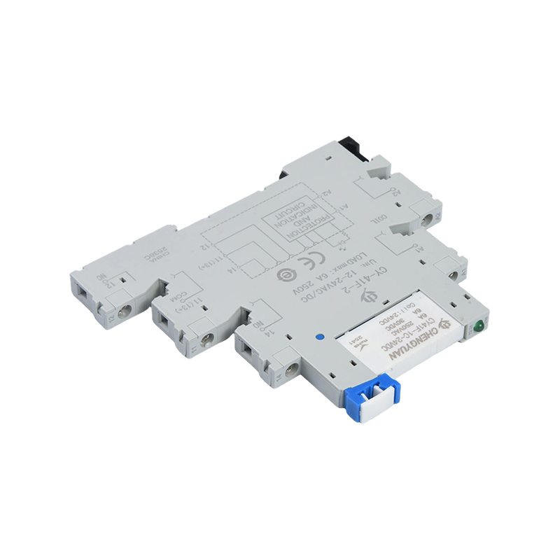
For a control cabinet crowded with DIN-rail devices, wiring every feedback point to a separate terminal increases assembly time and the risk of loose connections. A slim relay module with an integrated socket, screw terminals, and LED indication is often the cleaner solution for the PLC and interposing layer of the panel.
Auxiliary Contact Block or Interface Relay Module?
Both components switch control signals, but they are not interchangeable. The aux block belongs on the contactor and gives direct, mechanically coupled feedback. An interface relay module belongs on the DIN rail and gives signal conversion, electrical isolation, and a visible LED for the PLC cabinet. Most machines need both: the aux block on the power device, the relay module in the control cabinet.
Use an auxiliary block when the signal must reflect the true main-contact position, when the circuit is part of an interlock path, or when no rail space is available. Use a relay module when the panel is built around DIN-rail terminals, when an LED indicator shortens troubleshooting, or when the controller bus must stay isolated from the power circuit. The company industrial control modules are designed for this layer, with terminal blocks and LED state indication ready for cabinet wiring.
The radar chart compares an auxiliary contact block mounted on a contactor with an interface relay module mounted on DIN rail across six selection criteria. The aux block scores higher in contact rating for direct coil switching, takes no rail space, and is the lower-cost solution per function. The relay module scores higher in wiring convenience, because the socket and screw terminals arrive as one product, and in LED status indication. Both provide full galvanic isolation between the switched circuit and the driven circuit. The practical conclusion is that a motor starter should keep its auxiliary block for direct feedback and interlocking, while the PLC cabinet should use relay modules for signal distribution. Used together, they give the most reliable circuit and the fastest troubleshooting path.
The failures you will see in the field usually come from a small set of repeated mistakes.
Choosing only NO contacts and later adding an external relay to create one NC path, which complicates the wiring and adds a failure point.
Ignoring the AC-15 category and using the bare 10 A figure as if it applied at every voltage.
Switching a DC solenoid directly with the aux contact without checking the DC rating; DC arcs persist longer and cut the endurance dramatically.
Mounting the block loosely so the mechanical coupling wears and the feedback becomes intermittent.
Buying unmarked blocks without IEC or UL marking, where the contact material and endurance cannot be verified.
The procurement risk is real: the cheapest block may have no stated endurance and no utilization category. In a control circuit, an unreliable aux contact is worse than none at all, because it reports a false state instead of a clear one.
Conclusion
An auxiliary contact block is a small component with an outsized role. It tells the controller the truth about a switching device, builds holding and interlock logic, and keeps control signals out of the power path. Selecting one comes down to four checks: the voltage class, the AC-15 current rating, the contact arrangement, and the endurance at the real switched current. For DIN-rail control panels, combine auxiliary blocks on the contactors with relay modules in the cabinet, and verify the marking of every block before installation. If your design needs a confirmed rating or a specific terminal layout, compare the current rating of the available blocks and request a quote directly from the manufacturer.
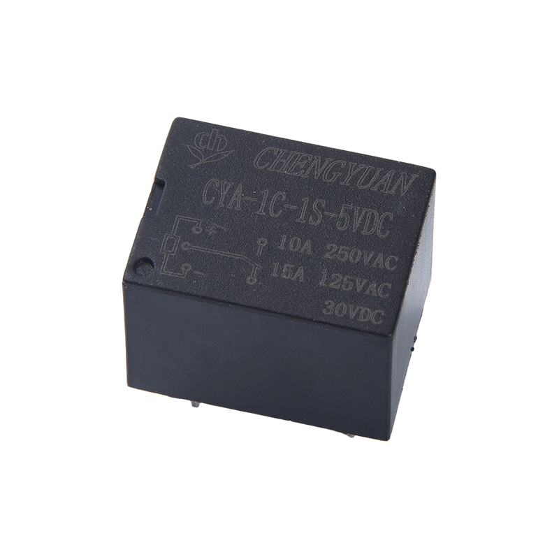
The CYA-S Relay (also known as Magnetic Latching Relay, 3F Latching Relay, Single and Double Coil Magnetic Latching) belongs to the CYA-S and CYF-S (3F/14F) series of magnetic latching relays. Compare...

 English
 中文简体
中文简体 Español