A 400/5 current transformer on a feeder tells a panel builder almost nothing until the secondary burden is chosen. The same unit can read within 0.5 percent on one meter and drift on another, and the difference is usually not the CT at all. The rule behind it is short: a current transformer delivers a secondary current fixed by the turns ratio, and it only behaves predictably while the secondary circuit stays close to a short circuit.
That one sentence explains accuracy, wiring practice, and the reason an open secondary can destroy insulation and injure people. Here is the mechanism first, then the practical consequences for metering, protection, and the relay hardware downstream.
The Core Mechanism: A Transformer Designed to Work Into a Near Short
Any transformer couples two windings through a shared magnetic core. What separates a current transformer is how it is applied. The primary is the conductor being measured, either passing once through a window or wound with several turns. The secondary carries many more turns, often hundreds, and is normally closed through a low value burden, a relay coil, or a shorting link.
Alternating primary current creates an alternating flux in the core. That flux links the secondary winding and induces a voltage across it. Because the secondary circuit has very low impedance, the induced voltage drives current instead of building up across an open gap. With negligible excitation current, the ampere turns balance: primary current times primary turns equals secondary current times secondary turns. Divide through by the secondary turns and the secondary current is simply the primary current divided by the turns ratio.
For a 400/5 unit, 400 A in the primary produces 5 A in the secondary. At 80 A primary the secondary carries 1 A. The relationship stays linear while the core can still magnetise in proportion to the primary current, and it stops being linear once the core saturates. Everything practical about CT selection, from accuracy class to accuracy limit factor, is really a statement about how far and how linearly that core can go.
From Alternating Flux to a Readable Number
The chain from busbar current to a displayed ampere value has five links.
- The primary conductor carries alternating current and magnetises the core.
- The changing flux induces a voltage in the secondary winding, proportional to the number of turns and the rate of flux change.
- The secondary current flows through the burden, and that burden converts current into a voltage. A 5 A secondary passing through a 0.1 ohm resistor develops 0.5 V.
- The meter or protective relay measures that voltage and multiplies it by the ratio and the burden value to report primary current.
- A small part of the primary current is spent magnetising the core rather than reaching the burden. This excitation current is the source of ratio error and phase displacement, and it grows as the core approaches saturation or the burden rises.
Phase displacement matters more than many buyers expect. A CT with a phase error of 30 minutes will shift the measured phase angle, which is harmless on a simple ammeter but adds real error to a power or energy measurement, especially at low power factor. That is why metering cores and protection cores are usually separate windings in the same housing.
Ratio, Burden and Accuracy Class in Practice
Four numbers decide most of the behaviour, and they interact. A generous ratio with a heavy burden can perform worse than a tighter ratio with a light burden.
Indicative values only; final selection depends on connected burden, cable length and system fault level.
| Parameter |
What it describes |
Common field values |
Practical effect |
| Rated ratio |
Nominal scaling between primary and secondary current |
100/5, 400/5, 1000/1 |
Sets the scaling constant used by the meter or relay |
| Rated burden |
Total impedance the secondary can drive while staying within its accuracy class |
5 VA, 10 VA, 15 VA |
Oversized burden increases error and brings saturation closer |
| Metering class |
Percentage error at rated current under defined conditions |
0.2, 0.5, 1.0 |
0.2 class suits billing and sub-metering, 1.0 suits indication only |
| Protection class |
Composite error plus accuracy limit factor, written as 5P10 or 10P20 |
5P10, 5P20, 10P20 |
The limit factor states how many times rated current the core can carry before error exceeds the stated band |
| Secondary current |
Nominal output level of the winding |
1 A or 5 A |
1 A suits long cable runs, 5 A suits short runs and existing panels |
Two orders of magnitude matter here. VA burden is specified at rated secondary current, so the same 5 VA burden is a very different load at 1 A than at 5 A. A 5 VA burden at 5 A means 0.2 ohm total loop impedance. The same 5 VA at 1 A means 5 ohm, which is why 1 A secondaries tolerate much longer cable runs before accuracy suffers.
Why an Open Secondary Is Dangerous
Open the secondary of an energised CT and the demagnetising ampere turns disappear. All the primary current becomes excitation current, flux climbs far past the design knee point, and the core saturates hard. The result is a peak voltage across the open terminals that can reach kilovolts, core heating, insulation stress, and a shock hazard on what is normally a 5 A circuit.
- Never remove a meter or relay from a live CT secondary without first shorting the winding at a test terminal block.
- Never fit a fuse in a CT secondary circuit. A blown fuse creates exactly the open circuit the CT cannot tolerate.
- Use dedicated shorting links or test blocks so the secondary can be bridged before any instrument is disconnected.
- Treat the secondary terminals as live whenever the primary is energised, regardless of what the meter reads.
Window, Wound, Split-Core and Toroidal
The mechanical form follows the installation, not the electrical theory. A window or bar type passes the primary cable or busbar straight through the centre, which keeps the primary isolated and makes ratio changes a matter of adding primary turns. A wound primary has the conductor built in, which suits low ratios where a single pass would give an impractical secondary current. Split-core units clamp around an existing cable for retrofit work in occupied buildings, at some cost in accuracy and repeatability because the core joint introduces a small air gap. Toroidal cores are compact and give a low leakage flux, which suits crowded enclosures and sensitive measurement.
Whatever the shape, the electrical requirement is unchanged: the secondary must be closed through a defined burden, and the core must have enough material and cross section to stay linear up to the currents that actually occur.
Where the Secondary Signal Goes Next
A 1 A or 5 A secondary usually lands on one of three things: a meter, a transducer, or a protective relay. In a switchgear panel, the CT feeds an overcurrent relay, and that relay's output has to become a switching action capable of energising a trip coil or signalling a PLC input. Interposing relays and rail-mounted control modules do that translation, taking a low-energy contact and switching a load with proper contact rating and isolation. A DIN rail module such as a 14F rail unit with 16 A contacts is a typical choice when the trip circuit must be driven from a compact panel.
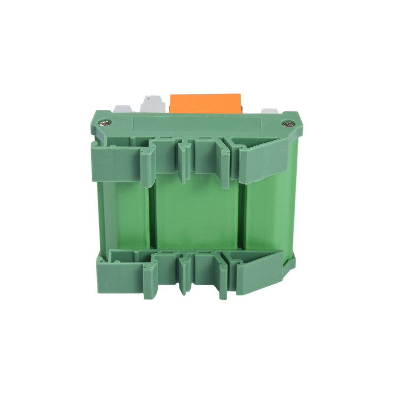 MCYF3 14F Rail-Mounted 16 A Relay ModuleRail-mounted 16 A relay module for compact panels, translating low-energy control contacts into higher-power switching with modular channel options.View Product →
Test benches and calibration rigs add a second requirement: isolation between the measurement side and the high voltage side. Dry reed relays are often used here because their sealed contacts switch cleanly at low signal levels and can hold off several kilovolts between coil and contact. The selection logic for that part of the circuit is covered in a separate note on reed relay applications, and it applies directly to CT test sets and high voltage measurement front ends.
 CYHVR 14 kV/20 kV High-Voltage Reed RelayHigh-voltage reed relay for test benches and measurement front ends, providing sealed-contact isolation and 3 A switching in high-voltage DC circuits.View Product →
Where a trip or status command is a short pulse rather than a continuous energisation, a magnetic latching relay keeps its state after the coil pulse ends. That removes continuous coil current from the panel, cuts heat inside the enclosure, and keeps the last commanded state through a supply interruption, which matters when the command came from a protection event.
 CYF1-S 16 A Magnetic Latching Relay16 A magnetic latching relay for pulse-driven commands, consuming coil power only during switching and retaining contact state through supply interruption in compact panels.View Product →
Read together, these three stages form the usual chain: the CT scales current down, the protection or measurement device decides, and a relay converts that decision into a contact that can be trusted in the field. The CT is the only part of the chain that cannot be replaced by a setting change, so it deserves the most careful specification.
Specifying a CT Without Guesswork
A short checklist avoids most of the mistakes seen in panel design reviews.
- Start from the maximum normal load and the prospective fault current, not from the cable size.
- Pick a ratio that puts normal load at roughly 60 to 80 percent of rated primary current, so the reading sits in the accurate part of the curve.
- Add up the real burden: meter input, relay coil, terminal resistance, and both legs of the connecting cable.
- Match the accuracy class to the purpose. Billing and sub-metering justify 0.2 or 0.5 class; indication only rarely does.
- For protection cores, check the accuracy limit factor against the actual fault level, not against the ratio alone.
- Confirm the secondary current against cable length. Long runs of 5 A wiring lose accuracy to resistance that a 1 A secondary would tolerate.
- Plan the shorting terminals and label them before commissioning, not after the first meter replacement.
Buyers who handle both relays and current transformers on the same project can cross-check the burden figures quickly, since a relay coil rating and a CT burden rating are expressed in the same units. General questions about matching relay coils to control circuits are answered on the FAQ page.
The working principle of a current transformer is genuinely simple: alternating primary current drives flux, flux induces a secondary current, and the turns ratio sets the scale. The engineering difficulty sits at the edges of that principle, in saturation, burden, phase error and the open-circuit hazard. Get those four under control and the CT becomes what it should be, a passive and predictable scaling element between the power system and the low voltage logic that monitors and protects it.

 English
 中文简体
 Español