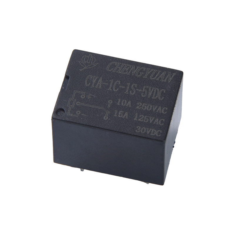
An ultrasonic sensor does not see an object. It listens for it. A transducer emits a brief pressure wave, usually above 20 kHz, then waits for a reflection. The delay between the outgoing burst and the returning echo is the measurement. That fact explains why ultrasonic sensing works in dirty air and why it can fail when a target is soft, angled, or too close.
The short answer: time of flight, divided by two
The sensor transmits a burst of high frequency sound. The burst reflects from a surface and returns. The sensor measures the round trip time, then halves the path:
distance = (speed of sound x echo time) / 2
At 20 C, sound travels at about 343 m/s. A 1 ms round trip represents about 17 cm of one way distance. Most sensors use 40 kHz or another frequency between 25 kHz and 200 kHz. Frequency affects beam shape, resolution, and reflection strength, but it does not set range by itself.
Two limits appear immediately. After transmitting, the transducer rings for a short time, so the receiver ignores returns during a blanking interval. This creates a minimum range. Echo strength also falls with distance, and soft or tilted targets return little energy. A sensor may reach 2 m on flat steel but far less on foam or cloth.
Inside the housing: transducer, driver, receiver, and timer
Most units share the same blocks, whether they are a small PCB module or a sealed barrel sensor.
Table 1: Core functional blocks in a typical ultrasonic distance sensor.
| Block |
Role |
Practical note |
| Piezoelectric transducer |
Converts electrical drive into sound and returning sound into voltage |
One element may transmit and receive, or separate units may be used |
| Driver |
Applies a short high frequency pulse train |
Burst length affects ringing and minimum range |
| Receiver and amplifier |
Raises a weak echo above electrical noise |
Gain often rises over time to compensate for distance |
| Comparator and timer |
Marks the echo threshold and measures elapsed time |
Threshold choice affects weak or angled targets |
| Output stage |
Converts time into distance, analog value, or switching signal |
Output type must match the control system |
A transceiver uses one piezoelectric element to transmit and receive. A two transducer design separates the functions and can shorten blanking, but it takes more space.
From burst to reading: the measurement sequence
A typical ranging cycle follows a fixed sequence:
- The driver applies a short high frequency pulse train to the transducer.
- The transmitter stops and the receiver is blanked while the element settles.
- The timer starts at a defined point in the transmit cycle.
- The receiver amplifies the echo and compares it with a threshold. Gain often rises over time.
- An echo crossing the threshold captures the timer value. The controller calculates distance and may average several readings.
- No valid echo before the timeout means no target, maximum range, or a fault depending on the output type.
Sound speed changes with air temperature. A common approximation is 331.3 plus 0.606 times the temperature in C, in m/s. A 10 C change alters speed by about 1.8 percent. At 2 m, that is roughly 3.6 cm of error without compensation. Filtering improves repeatability but adds delay, so a fast target needs a shorter average than a slow tank level.
Beam angle, target surface, and the limits of sound
An ultrasonic sensor produces a cone, not a laser point. The full beam angle may be roughly 10 to 60 degrees. A wide cone finds targets easily but also hears tank walls and conveyor frames. A narrow cone separates nearby objects better but needs careful alignment.
Target material matters as much as distance. Hard, flat, perpendicular surfaces return strong echoes. Foam, cloth, loose powder, and open cell materials absorb sound. A tilted plate can deflect the echo away. A small target can be weak even at close range. In level work, thick foam may be read instead of the liquid below it.
Air currents, steam, dust, and temperature gradients bend or scatter the beam. Several sensors mounted close together can cross talk. Triggering them in sequence is more reliable. Common failures include a bracket echo before the real target, a target inside the blanking distance, a soft or tilted surface, and acoustic noise from pneumatics.
Specifications that decide whether the sensor fits
Datasheet range needs context. A 6 m rating may require a large flat plate in controlled air. Check minimum range, beam angle, and target size at the working distance, then compare the electrical ratings.
- Range and minimum range: the useful span between blanking distance and the largest reliable echo.
- Beam angle: the cone the sensor can hear, usually stated at a specified attenuation.
- Resolution and repeatability: the smallest reported change and the spread of repeated readings. These are not the same as absolute accuracy.
- Response time: the delay from a target change to a stable output, including averaging.
- Output type: analog 4-20 mA or 0-10 V, or PNP, NPN, and relay contacts for switching.
- Supply and load: voltage range, current consumption, and the load the output can drive.
- Environmental rating: IP rating, chemical compatibility, temperature range, and face protection.
Resolution can mislead. A 1 mm display step may still have several millimeters of repeatability error. For switching, hysteresis and repeatability often matter more than absolute accuracy.
Where the sensor output goes in a machine control system
An ultrasonic sensor is one part of a control loop. It may measure tank level, detect a pallet, check roll diameter, or watch a web loop. The output goes to a PLC, controller, meter, or relay interface. Analog output suits level and position. PNP or NPN output suits presence and limit detection.
A relay stage helps when the sensor must switch a lamp, solenoid, alarm, or contactor, or when the controller and field circuit need separation. Coil voltage, contact form, contact rating, and panel space should be selected together. The industrial control modules on this site include rail mounted formats for this layer.
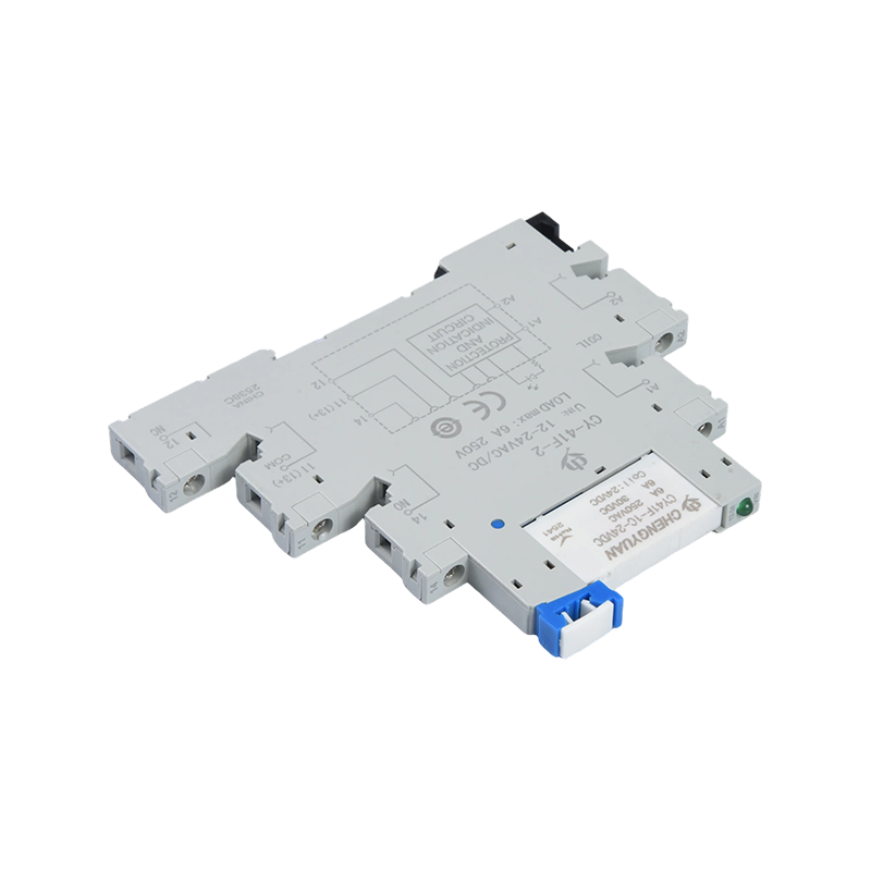 M41F DIN-Rail Relay Module, 6 A, Multi-ChannelDIN-rail relay module with 6 A contacts, multi-channel options, slim housing, built-in protection, and control-load isolation for panel relay stages.View Product →
A slim rail module saves space when a panel has many sensor points. A 14F module with a 10 A contact may suit a small pump, fan, or alarm. The module does not improve the acoustic reading, but it determines whether the signal can switch the load safely.
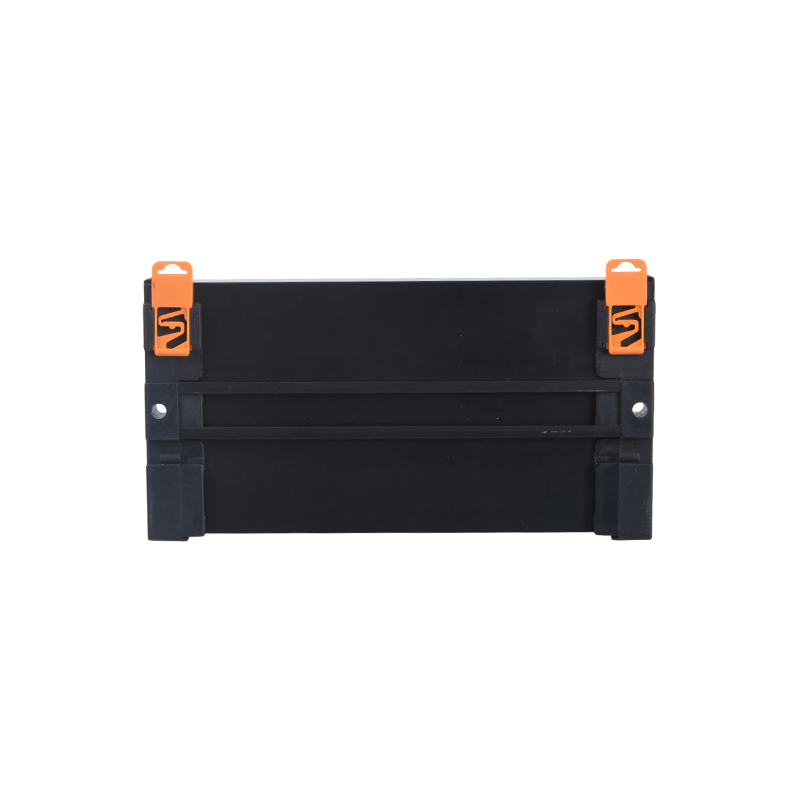 MCYF1 DIN-Rail Latching Relay Module, 10–16 ADIN-rail module using CYF1-S latching relays, offering up to 16 channels at 10–16 A and zero static power for energy-efficient load switching.View Product →
Check coil current against the sensor output rating, contact rating against the load, and isolation against the panel design. A transistor output rated for 100 mA should not drive a larger relay coil directly. A contact rated for resistive load may need derating for a motor or solenoid.
Installation checks that prevent most problems
A bench test in still air is a weak predictor of real machine performance. Run these checks with the machine operating.
- Mount the sensor perpendicular to the expected target surface.
- Draw the beam cone on the drawing and check for walls, guards, and frame members.
- Keep the target outside the blanking distance during filling or retraction.
- Test the worst target material and the worst angle, not just flat metal.
- Compare readings with a physical measurement at minimum and maximum range.
- Run pumps, fans, and pneumatics to expose acoustic noise and cross talk.
- Confirm output load, relay coil, and controller input compatibility.
- Record repeatability after warm up to catch temperature drift.
If readings jump, fix the acoustic path first. Move away from a side wall, use a narrower beam, or change the angle. If the target is soft, consider another sensing principle. Filtering hides bad echoes; it does not create a clean one.
The practical takeaway
An ultrasonic sensor works by timing a sound burst and its echo. The formula is simple, but the usable result depends on blanking distance, beam angle, target reflectivity, temperature, and the output interface. Select for the real target and environment, then make sure the control layer can drive the load.
For help matching a sensor signal to a rail mounted relay module, contact the team with the output type, coil voltage, contact rating, and panel space. Those four details usually settle the interface choice quickly.

 English
 中文简体
 Español