Compressor Contactor Guide: How It Works, Failure Signs, and ReplacementCompressor Contactor Guide: How It Works, Failure Signs, and ReplacementCompressor Contactor Guide: How It Works, Failure Signs, and ReplacementCompressor Contactor Guide: How It Works, Failure Signs, and ReplacementCompressor Contactor Guide: How It Works, Failure Signs, and ReplacementCompressor Contactor Guide: How It Works, Failure Signs, and ReplacementCompressor Contactor Guide: How It Works, Failure Signs, and ReplacementCompressor Contactor Guide: How It Works, Failure Signs, and ReplacementCompressor Contactor Guide: How It Works, Failure Signs, and ReplacementCompressor Contactor Guide: How It Works, Failure Signs, and ReplacementCompressor Contactor Guide: How It Works, Failure Signs, and ReplacementCompressor Contactor Guide: How It Works, Failure Signs, and ReplacementCompressor Contactor Guide: How It Works, Failure Signs, and ReplacementCompressor Contactor Guide: How It Works, Failure Signs, and ReplacementCompressor Contactor Guide: How It Works, Failure Signs, and ReplacementCompressor Contactor Guide: How It Works, Failure Signs, and Replacement
News
Home / News / Industry News / Compressor Contactor Guide: How It Works, Failure Signs, and Replacement
Compressor Contactor Guide: How It Works, Failure Signs, and Replacement
A commercial refrigeration technician once traced a compressor lockout to a small electromagnetic switch that had cycled more than 200,000 times. The compressor itself was fine, the refrigerant charge was fine, and the only failed part was the contactor controlling the motor. That sequence repeats in thousands of HVAC and refrigeration systems every year. A compressor contactor sits between the control circuit and the motor, and when it degrades, the rest of the system usually suffers before anyone notices. Understanding how it works, why it fails, and how to pick the correct replacement is the shortest path to fewer service callbacks.
What Is a Compressor Contactor and Why It Matters
A compressor contactor is an electrically operated switch built for the specific demands of motor loads. Unlike an ordinary toggle switch or a small signal relay, it has to break and make a highly inductive circuit carrying locked-rotor current. The main components are the coil, the movable contact assembly, and the arc-resistant switching chamber. The coil terminals are normally labeled A1 and A2. When the control circuit energizes the coil, the magnetic field pulls the armature down and closes the line and load contacts. When the control signal stops, a spring pushes the contacts back open.
Startup current profile of a typical compressor motor
The current trace above shows why compressor duty is so hard on contacts. When the motor is stationary, it behaves almost like a short circuit, drawing locked-rotor current that can reach six to eight times the full-load amperage. That surge lasts only a fraction of a second, but it produces an intense arc when the contacts separate and a localized hot spot when they close. The arc erodes contact material, and the inrush heats the contact surface faster than the metal can dissipate it. A contactor selected only for the motor's running current will eventually weld its contacts together or lose enough material to create a dangerous voltage drop. The contact rating must therefore be based on the worst-case inrush, not on the steady-state value.
Why Compressor Contactors Fail
The conclusion first: most compressor contactor failures come from electrical contact wear, coil damage, mechanical fatigue, or poor terminations. Pitting is the most common failure because every switching event draws an arc that erodes the silver facing. Coil burnout usually follows undervoltage operation, because a coil that cannot close fully keeps drawing high current and overheats. Welded contacts are typically the end result of repeated inrush events or a chattering contactor that never stops arcing. Loose terminals are less common but the most dangerous, because they create heat that can spread to the wiring.
Distribution of compressor contactor failure causes
The distribution above reflects the experience of field-service organizations with thousands of compressor contactor replacements. Pitted contacts account for roughly one in three failures, which fits the physics of repeated arcing. Coil burnout is second and is often preventable, since it tends to follow a control circuit supplying voltage that is too low or excessively noisy. Welded contacts and mechanical wear together make up about a third of the remaining cases. Loose terminations are the smallest category but the riskiest, because a bad connection produces heat and, eventually, a melted terminal block. When you inspect a failed contactor, matching the visible damage to these categories points to whether the root cause is in the contactor itself or elsewhere in the system.
A failed contactor rarely fails silently. The table below maps common warning signs to the likely cause, the verification step, and the appropriate response.
Common compressor contactor warning signs and the steps to confirm each one.
Symptom
Likely Cause
What to Verify
Practical Response
Buzzing or chattering
Low coil voltage or a broken shading coil
Measure coil voltage during pull-in
Fix the control voltage or replace the contactor
Contacts welded closed
Repeated high inrush or heavy erosion
De-energize, then inspect contact faces
Replace the contactor and check the compressor draw
Hot terminal block
Loose terminations or overcurrent
Check torque and compare amp draw with the rating
Retorque to specification or replace the terminal
Intermittent compressor starts
Pitted contacts causing high resistance
Test continuity across line and load terminals
Replace the power contact assembly
No switching at all
Open coil or no control signal
Measure coil resistance and control voltage
Replace the coil or repair the control wiring
How to Select a Compressor Contactor
Selecting a compressor contactor comes down to three decisions: coil voltage, contact current rating, and contact material. Get the first two right and the contactor will probably outlive the compressor. Coil voltage must match the control circuit, commonly 24 V AC in residential HVAC, 120 V or 240 V AC in commercial panels, and 24 V DC in PLC-based controls. The contact rating must exceed the compressor full-load amperage and also survive the locked-rotor current during startup. The contact material determines how long the contact surfaces resist arc erosion and welding.
Relative electrical life of common contact materials under AC-3 motor duty
The bar chart compares typical electrical endurance for four silver-based contact materials when switching motor loads. Silver cadmium oxide (AgCdO) has historically delivered the longest life, but its use is restricted in many countries because cadmium is toxic. Silver tin oxide (AgSnO2) is the modern substitute and offers excellent welding resistance, which makes it the preferred choice for compressor contactors. Silver tungsten (AgW) handles very high inrush currents but tends to develop higher contact resistance as it wears. Silver nickel (AgNi) is economical and fine for moderate switching duty, but it erodes faster under the extreme inrush of a locked compressor rotor. For new designs, AgSnO2 is the most balanced choice between performance and regulatory compliance.
Matching the Coil Voltage to the Control Circuit
Common compressor contactor coil voltage options include:
24 V AC: residential HVAC and small refrigeration circuits
120 V AC: commercial package units and split systems
208/240 V AC: larger commercial and light industrial panels
24 V DC: PLC and building automation outputs
Most contactors must see about 85% of the nameplate coil voltage to pull in. If the control circuit dips below that during compressor startup, the contactor will chatter and burn its coil. Measure the coil voltage at the terminals while the unit is starting.
Testing and Maintaining a Compressor Contactor
Testing a compressor contactor takes about ten minutes and needs only a multimeter and a screwdriver. Use this sequence whenever a compressor stops starting or the panel starts buzzing:
Disconnect all power sources and lock out the panel.
Measure coil resistance between A1 and A2 and compare it with the nameplate value.
Energize the coil or close the contacts manually and test the voltage drop across each line-load pair.
Confirm the contacts open cleanly when the coil is de-energized.
Inspect the contact faces for pitting, silver transfer, or welding.
Verify that terminal screws meet the torque values printed on the contactor.
A coil reading within 10% of the nameplate resistance is usually healthy. Voltage drop across a closed contact pair should be nearly zero; anything above a few hundred millivolts at rated current signals pitting. Do not file or clean modern silver contacts. Contaminated contact surfaces arc worse and fail sooner.
Relay-Based Alternatives for Compressor Control Panels
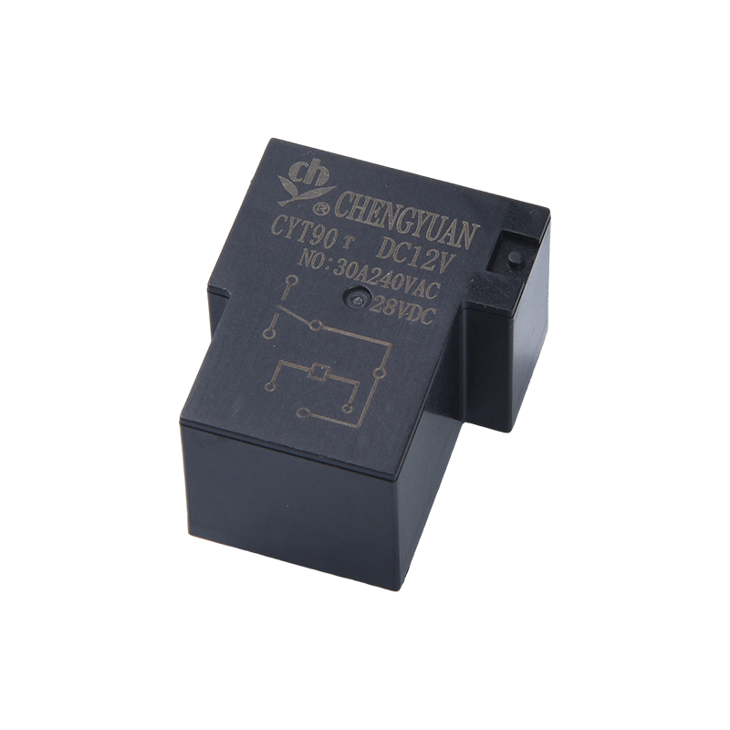
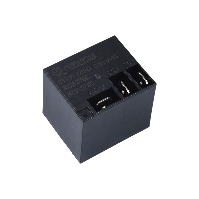
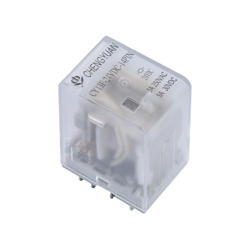
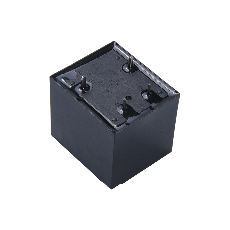
Not every compressor application needs a traditional contactor. Many OEMs building compact compressor control boards use high-current PCB-mount relays when the motor is small and the switching cycle is moderate. These relays provide the same electrical isolation in a fraction of the panel space. The CY T90 series is a 30 A SPDT relay, and the CY T91 series extends that capacity to 40 A. For larger systems or high-cycle PLC outputs, the CY13F industrial power relay offers 4PDT switching in a socket-mountable package.
Relay series comparison for compressor switching duty
The radar chart compares three relay series that can be used for compressor switching duty inside compact control panels. The T91 series carries the highest contact rating and the strongest inrush handling margins, making it the obvious first choice for motors with a high locked-rotor ampere value. The T90 series offers a 30 A rating with very good mechanical life, which suits smaller compressors and heat pump fan motors. The CY13F industrial relay leads in electrical and mechanical endurance, so it fits high-cycle applications where the panel already uses socket-mounted relays. Mounting density and control flexibility vary between the series, so the final pick depends on whether you have PCB space or DIN-rail space, and whether your control output is a conventional thermostat or a PLC. A relay selected too close to its limit will behave exactly like a cheap contactor: it will heat, chatter, and eventually fail at the worst moment.
Ningbo Chengyuan Chuangke Electronics Co., Ltd., known as CY Relays, has manufactured electromagnetic relays and industrial control modules for nearly three decades. The company holds utility-model patents on magnetic-latching and snap-fit relay structures, which reflect a practical focus on contact stability and production consistency. Its catalog covers general-purpose electromagnetic relays, reed relays, magnetic-latching relays, and relay modules. The manufacturing history and quality principles are documented on the about page. If you are sourcing a replacement contactor or designing a relay-based compressor controller, asking for endurance data and coil options before ordering prevents most field failures.
Before buying a compressor contactor or a relay-based substitute, run through this checklist:
Confirm the control coil voltage against the actual control circuit, not the label on the old part.
Calculate the compressor full-load amperage and locked-rotor amperage from the motor nameplate.
Pick a contact rating that covers the locked-rotor value, especially for making duty.
Verify contact material suits the switching frequency and inrush characteristic.
Account for ambient temperature, humidity, and panel vibration.
Ask the supplier for mechanical life, electrical life, coil options, and terminal layout.
A compressor contactor is a small component with a critical job. When correctly specified and maintained, it switches reliably for years. When it is undersized or ignored, it can take the compressor down with it. The motor always asks for current, the contacts try to deliver it, and the weakest point fails first. Give that weak point the right ratings and the rest of the system keeps working. If you need help matching a relay to your compressor load, the contact page is a good place to start a technical conversation.
The CYA-S Relay (also known as Magnetic Latching Relay, 3F Latching Relay, Single and Double Coil Magnetic Latching) belongs to the CYA-S and CYF-S (3F/14F) series of magnetic latching relays. Compare...
In the power switching field, the CYT91 Relay is a compact, high-capacity relay designed to handle high current challenges. Compared to relays of similar size, this model achieves a current switching ...
The M41F Relay Module is a rail-mounted relay module offering various channel configurations from single to 32 channels, and features built-in protection circuits supporting 6A load switching. This pr...

 English
 中文简体
中文简体 Español